Yes, Paul indeed gave a great overview of the converter boards currently available and we should be grateful to him. Now, if you care about silent operation, you may want to refer to #1,409 where I present my own monitor conversion. Note the simplicity and cleanliness of the result. A similar solution should be possible even without soldering. It would imply two major departures: (i) using a standard power supply brick rather than the original unit and (ii) refraining from fitting the various buttons, LEDs, etc. to former data connector and camera slots. Instead, you would simply take the strip that comes with the R9A18 and attach it to the monitor case – inside or outside – next to the open RAM access door. Many such constructions presented in this forum can serve as sources of inspiration. Good luck!Thank you so much for the awesome breakdown! My only remaining question would be the necessity of a fan, that was kind of pushing me to the R1811 ...
Got a tip for us?
Let us know
Become a MacRumors Supporter for $50/year with no ads, ability to filter front page stories, and private forums.
DIY 5k Monitor - success :-)
- Thread starter fiatlux
- WikiPost WikiPost
- Start date
- Sort by reaction score
You are using an out of date browser. It may not display this or other websites correctly.
You should upgrade or use an alternative browser.
You should upgrade or use an alternative browser.
- Status
- The first post of this thread is a WikiPost and can be edited by anyone with the appropiate permissions. Your edits will be public.
Again, y’all are super helpful!
While I was thinking about doing the R1811, I had to check myself, as this is a totally unnecessary project that my wife is rolling her eyes at, so spending $300 on a board is probably unnecessary.
I did end up going with the JRY-FA1 for $150 shipped, so all in it’ll be about $350 total ($125 iMac, $150 board, $25 ifixit, $50 PSU/Dp-Tb3 cord).
I actually do have a question about any recommended PSUs. The FA1 listing didn’t give me dimensions for the power plug, it only says 24V. Would either of these work for a simple external setup?
As an Amazon Associate, MacRumors earns a commission from qualifying purchases made through links in this post.
I have an FA1 and can confirm it uses a standard 2.5 x 5.5mm barrel plug. It works on 12v too even though the specs say 24v. I messaged the AliExpress vendor and confirmed it supports 12v/24v.
I want to test using the iMac PSU but never got time to solder some wires between the PSU and the FA1 board, so I kept using the "temporary" solution (mean well PSU GST60A12). Consumes around 44-45 watts at full brightness.
I want to test using the iMac PSU but never got time to solder some wires between the PSU and the FA1 board, so I kept using the "temporary" solution (mean well PSU GST60A12). Consumes around 44-45 watts at full brightness.
The difference between using the JRY PBC on 12 or 24v.
If you ar going to use only monitor connect to Macmini or other pc_computer desktop....You only need 12v at 5 or 6Amp best.
In my mesurement test to 12v i need 3,5Amp without connect Fan Control and mid bright pannel.
But if you are going to connect a macbook and want to charguer battery, it need 24v 6A power supply.
For anyone interested in the JRY-FA1, please consider this board has 2 HDMI ports and 2 full size DisplayPort inputs, so there's no way of charging a MacBook when connected to it. I use a MacBook Pro M2 with a USB-C to DisplayPort 1.4 cable and it works correctly for displaying the full 5K60 (I believe at 10 bits but haven't been able to confirm), but it does not charge (as expected). The JRY-SA1 should be able to charge a MacBook when using the USB-C input.But if you are going to connect a macbook and want to charguer battery, it need 24v 6A power supply.
Sorry my pcb JRY-W9 is different, well if you don't have USB-C, only need 12v 5 o 6Amp so that it doesen´t get too hot.For anyone interested in the JRY-FA1, please consider this board has 2 HDMI ports and 2 full size DisplayPort inputs, so there's no way of charging a MacBook when connected to it. I use a MacBook Pro M2 with a USB-C to DisplayPort 1.4 cable and it works correctly for displaying the full 5K60 (I believe at 10 bits but haven't been able to confirm), but it does not charge (as expected). The JRY-SA1 should be able to charge a MacBook when using the USB-C input.
I've been working on setting up the speakers for the best possible sound quality. Here are my results:
- Woofer connected directly to amplifier, working as a full range speaker. It plays all the way to 20kHz, but with reduced output towards the highs. Checking distortion shows that it is working properly.
- Tweeter coupled with a capacitor of 4.7uF, same polarity as woofer. Measured several capacitor sizes, including reversing polarity, in order to find the best merging with the woofer. The tweeter has a rather low output, so combined with the woofer the highs are getting in the right ballpark.
- Once the hardware was connected as mentioned above, I've tailored the frequency response to my desired target curve, having a slight dip towards the high end. I'm using SoundSource for this. Towards the low end the woofer produces a Hugh amount of distortion if driven a bit harder, so I've reduced slightly the sound output between around 100-150Hz, to avoid getting very audible distortion.
The result is more than satisfying and spending money on the crossovers is not needed.
Without EQing the sound is rather horrible though, with an extreme elevation of more than 15dB between 200-400Hz. So EQing is a must, save on the crossovers.
Measuring setup ...

Yellow: Woofer alone, connected full range, R channel
Red: Tweeter alone, coupled by 4.7uF, R channel
Blue-green: Woofer and tweeter combined, R channel

Green: L+R combined, unaltered
Yellow: corrected

Settings in SoundSource

- Woofer connected directly to amplifier, working as a full range speaker. It plays all the way to 20kHz, but with reduced output towards the highs. Checking distortion shows that it is working properly.
- Tweeter coupled with a capacitor of 4.7uF, same polarity as woofer. Measured several capacitor sizes, including reversing polarity, in order to find the best merging with the woofer. The tweeter has a rather low output, so combined with the woofer the highs are getting in the right ballpark.
- Once the hardware was connected as mentioned above, I've tailored the frequency response to my desired target curve, having a slight dip towards the high end. I'm using SoundSource for this. Towards the low end the woofer produces a Hugh amount of distortion if driven a bit harder, so I've reduced slightly the sound output between around 100-150Hz, to avoid getting very audible distortion.
The result is more than satisfying and spending money on the crossovers is not needed.
Without EQing the sound is rather horrible though, with an extreme elevation of more than 15dB between 200-400Hz. So EQing is a must, save on the crossovers.
Measuring setup ...
Yellow: Woofer alone, connected full range, R channel
Red: Tweeter alone, coupled by 4.7uF, R channel
Blue-green: Woofer and tweeter combined, R channel
Green: L+R combined, unaltered
Yellow: corrected
Settings in SoundSource
Last edited:
Excellent analysis - the graphs are very informative. 👍
This is with a R9A18?
The R1811 has the same audio amp chip, other boards are different, but the speakers will act the same...
"...spending money on the crossovers is not needed."
What the crossovers give you is simple plug in wiring.
I have analysed/guessed the performance of the crossover in post #1202.
If you use the crossover with all jumpers A, B, C and D connected, them the performance is exactly as @5lives suggests.
The tweeter has 4.8µF in circuit, and the woofer is directly connected to the amplifier, as the inductor and third 100µF capacitor are shorted, so not in circuit.
When connected in this way the total impedance the woofer/tweeter present to the amplifier will be lower than 4Ω (ohms) at frequencies above the point where the tweeter comes into circuit - between 1 - 2 KHz on @5lives graph above. If this sounds clean and undistorted, then this is not a problem. 🙂
The inductor is best shorted out by the jumper, as it is way too high in value to work with 4Ω speakers (OK for 8Ω), and the 100µF capacitor is there to allow a further big external sub-woofer to be added, to roll off the bass form the small iMac woofer.
It seems the woofer may drop in impedance below 4Ω between 200-400Hz, and if this drop is below 3.2Ω then the amplifier data sheet says this is out of range.
Hence the distortion.
A Zobel Network correction circuit might correct this? (For those who are OCD about audio perfection...) 😁
The graphs @5lives has provided would help in the calculation!
For info, I think the iMac Pro speakers I used in my R1811 monitor have the same inherent distortion peak, but in the 125-250Hz range.
I have used eqMac to correct this.
EDIT: Just for clarity, the capacitors used with speakers should be audio grade ‘bi-polar’ (no polarity markings).
Electrolytic capacitors have a MTBF up to 10s of thousands of hours.
Polypropylene audio capacitors are more than 10 times better.
Last edited:
My wife is happy as the 5K Monitor is now hers, she uses it every day with a MacBook Air.I had to check myself, as this is a totally unnecessary project that my wife is rolling her eyes at, so spending $300 on a board is probably unnecessary.
Her advice: Just make two ...
I didn't understand everything 100% (I'm not an audio person) but I find that the iMac speakers (Mine are 2017) only sound like ok compared to my tiny MacBook Pro 2021 speakers witch sounds great.I have used eqMac to correct this.
Could you possibly please provide your settings for eqMac (SoundSource unfortunately costs something)?
I used the crossover boards in default settings. All 4 jumpers are set and only on the right side (seen from the front) I have exchanged the two cables. Would be cool if you could improve the sound.
I now also want to try to install a large fan as @usert888 did. The volume of the little one annoys me. Only I see a bit of the problem with the place.
///EDIT: In post #1,209 @Aiwi has already shared his eqMac settings. I'll try these.
Last edited:
I have iMac Pro speakers, so my eqMac settings are different.
eqMac requires payment for their 31-way equaliser (like SoundSource), but the free version has a 10-way equaliser, so you could copy a simpler 10-way setting from @5lives to get some improvement.
In the end it's all down to how it sounds...
A larger fan can run slower and more quietly, but be careful with the heatsink.
The thermal paste under the heatsink is very fragile, and if the heatsink moved the thermal paste will be dislodged, which will make heat transfer worse.
I haven't had any noise problems with my heatsink fan, but it usually runs even slower as I have a variable speed controller.
The temperature sensor is (carefully!) clipped to the bottom right of the heatsink, and connects to a controller.
Last edited:
Thank you very much.
With the eqMac settings it sounds much better. Very good!
I installed the original iMac fan. Can't I solder a second 150Ohm resistor in between to make the small fan run even slower? Or does it not turn at all anymore? In itself, I would like to save myself the tinkering with the big fan. But I don't like the sound. Whereby the RAM opening is also still open...
He estado trabajando en la configuración de los altavoces para la mejor calidad de sonido posible. Aquí están mis resultados: - El woofer conectado directamente al amplificador, funcionando como un altavoz de rango completo. Reproduce hasta 20 kHz, pero con una salida reducida hacia los agudos. La comprobación de la distorsión muestra que está funcionando correctamente. - Tweeter acoplado con un condensador de 4,7uF, misma polaridad que el woofer. Se midieron varios tamaños de condensador, incluida la polaridad inversa, para encontrar la mejor fusión con el woofer. El tweeter tiene una salida bastante baja, por lo que combinado con el woofer, los agudos están llegando al estadio correcto. - Una vez que el hardware se conectó como se mencionó anteriormente, he adaptado la respuesta de frecuencia a mi curva objetivo deseada, teniendo una ligera caída hacia el extremo superior. Estoy usando SoundSource para esto. Hacia el extremo inferior, el woofer produce una gran cantidad de distorsión si se conduce un poco más fuerte, por lo que he reducido ligeramente la salida de sonido entre alrededor de 100-150 Hz, para evitar obtener una distorsión muy audible. El resultado es más que satisfactorio y no es necesario gastar dinero en los crossovers. Sin embargo, sin ecualización, el sonido es bastante horrible, con una elevación extrema de más de 15dB entre 200-400 Hz. Así que la ecualización es imprescindible, ahorre en los crossovers. Configuración de medición... View attachment 2434896 Amarillo: Woofer solo, rango completo conectado, canal R Rojo: Tweeter solo, acoplado por 4.7uF, canal R Azul-verde: Woofer y tweeter combinados, canal R View attachment 2434897 Verde: L+R combinados, inalterados Amarillo: corregido View attachment 2434898 Configuración en SoundSource View attachment 2434900
I'm a little rusty but I still have a bit of control over the issue
")
I was measuring the resonance frequency in both, the Woofer is at 250Hz and the Tweeter at 2.7Khz both ar 4 ohms, and i was thinking of making the 12db and cutting at 4.5 or 5.6Khz Because on Aliexpress the dividers are huge to handle high powers that are unnecessary, and they do not specify whether they are 4 or 8 ohms, they simply generalize.
For 4500hz 12dB i need 6,3mF + 0,2mH or simple crossover 6db/Oct 8.8mF and 0,14mH, and... too maybe dampen that 250Hz resonance, what do you think?
Am using the R9A18 driver.Excellent analysis - the graphs are very informative. 👍
This is with a R9A18?
The R1811 has the same audio amp chip, other boards are different, but the speakers will act the same...
"...spending money on the crossovers is not needed."
What the crossovers give you is simple plug in wiring.
I have analysed/guessed the performance of the crossover in post #1202.
If you use the crossover with all jumpers A, B, C and D connected, them the performance is exactly as @5lives suggests.
The tweeter has 4.8µF in circuit, and the woofer is directly connected to the amplifier, as the inductor and third 100µF capacitor are shorted, so not in circuit.
When connected in this way the total impedance the woofer/tweeter present to the amplifier will be lower than 4Ω (ohms) at frequencies above the point where the tweeter comes into circuit - between 1 - 2 KHz on @5lives graph above. If this sounds clean and undistorted, then this is not a problem. 🙂
The inductor is best shorted out by the jumper, as it is way too high in value to work with 4Ω speakers (OK for 8Ω), and the 100µF capacitor is there to allow a further big external sub-woofer to be added, to roll off the bass form the small iMac woofer.
It seems the woofer may drop in impedance below 4Ω between 200-400Hz, and if this drop is below 3.2Ω then the amplifier data sheet says this is out of range.
Hence the distortion.
A Zobel Network correction circuit might correct this? (For those who are OCD about audio perfection...) 😁
The graphs @5lives has provided would help in the calculation!
For info, I think the iMac Pro speakers I used in my R1811 monitor have the same inherent distortion peak, but in the 125-250Hz range.
I have used eqMac to correct this.
EDIT: Just for clarity, the capacitors used with speakers should be audio grade ‘bi-polar’ (no polarity markings).
Electrolytic capacitors have a MTBF up to 10s of thousands of hours.
Polypropylene audio capacitors are more than 10 times better.
Ok, there's really nothing simple about using the crossovers, in contrary - if you know how to use a soldering iron.
The distortion is not coming from the amplifier, it's that poor little woofer suffering to produce frequencies it is not meant for. I've changed my Hipass filter later to start rolling off at 160Hz, this way the distortion is reduced further without really loosing anything sound wise.
Your iMac Pro speakers have slightly bigger woofers, so they start suffering at a bit lower frequencies.
For those using EQ, make sure you add a Hipass too, to block feeding unnecessary energy into the woofer for frequencies it cannot reproduce.
Ya, with the free version of eqMac, the sound can be sure improved a lot compared to not using an EQ at all. Try mimicking the opposite curve from my picture with the unaltered frequency response.
Ya, good point on the capacitor choice. The cheapest foil capacitor will do (non-electrolytic).
@Xarl-li your values for the tweeter capacitor and inductor are similar to the ones I used.
To reduce the woofer resonance you you would need a large capacitor in series with it. Bigger than the 100µF one in the AliEx crossovers. 200µF or more.
But that would remove all low frequencies, unless you use it in a Zobel Network with a resistor to go with it (both in parallel with the woofer).
To reduce the woofer resonance you you would need a large capacitor in series with it. Bigger than the 100µF one in the AliEx crossovers. 200µF or more.
But that would remove all low frequencies, unless you use it in a Zobel Network with a resistor to go with it (both in parallel with the woofer).
Last edited:
You sure can try a second order crossover for the tweeter, not sure it will do much though, since we'll have to use an EQ anyways for a proper outcome.I'm a little rusty but I still have a bit of control over the issue
I was measuring the resonance frequency in both, the Woofer is at 250Hz and the Tweeter at 2.7Khz both ar 4 ohms, and i was thinking of making the 12db and cutting at 4.5 or 5.6Khz Because on Aliexpress the dividers are huge to handle high powers that are unnecessary, and they do not specify whether they are 4 or 8 ohms, they simply generalize.
For 4500hz 12dB i need 6,3mF + 0,2mH or simple crossover 6db/Oct 8.8mF and 0,14mH, and... too maybe dampen that 250Hz resonance, what do you think?
The resonance frequency of a speaker will not lead to mechanical resonance, the amplifier is just seeing a higher resistance there, and eventually cannot deliver as much power into the speaker like in the areas outside of the resonance. But in our case that is not an issue.
Seguro que puedes probar un crossover de segundo orden para el tweeter, aunque no estoy seguro de que haga mucho, ya que tendremos que usar un ecualizador de todos modos para un resultado adecuado. La frecuencia de resonancia de un altavoz no conducirá a la resonancia mecánica, el amplificador solo está viendo una mayor resistencia allí, y eventualmente no puede entregar tanta potencia en el altavoz como en las áreas fuera de la resonancia. Pero en nuestro caso eso no es un problema.
Thanks, yes, I was thinking about the zobel network, and maybe it's not worth the effort.
6 dB crossover only and Eq app user.
@PaulD-UK ya, I can see that hump! : )
But I think it is the resonance of the enclosure it is in, some kind of bass reflex, otherwise that little woofer would not be able to produce much low frequency output. And in general the bass reflex enclosure is tuned around the resonance frequency of the speaker in order to extend the output of the speaker into the range where it would struggle to perform because of its elevated resistance (impedance). At least this is my understanding ...
Maybe there is a confusion between the electrical and mechanical resonance. The electrical resonance can be observed by measuring the impedance, and that strong impedance peak is at the electrical resonance of the speaker "motor". In our case this is at 250Hz, according to @Xarl-li.
The mechanical resonance happens towards the opposite end of the frequency spectrum, and is where the movement becomes so fast, that the cone of the speaker cannot act anymore "in one piece", so it starts wobbling in itself. Since this woofer is so small though, this mechanical resonance does not happen in the audible frequency range and we can use it till 20kHz. Otherwise we'd have to cut it off before the resonance frequency with a low pass filter.
Have a look at the distortion graph, the distortion peak does not correlate with (electrical) resonance frequency. If the speaker would play louder there because of mechanical resonance, then the distortion would be exactly there. In our case, the distortion shows the woofer is just about to give up reproducing those low frequencies.

Also look at the waterfall spectrum, if a mechanical resonance would be the reason for the elevated output at 200-400Hz, than there would be a considerable delay and some ugly artifacts there. There is some delay compared to the rest of the graph, but that is based on the much higher loudness in that range.

Edit: Ok, I've looked up the nomenclature, and you are right Paul, there is another kind of a resonance there that apparently correlates to the impedance peak, the one you are probably talking about. Difficult subject ... : )
But I think it is the resonance of the enclosure it is in, some kind of bass reflex, otherwise that little woofer would not be able to produce much low frequency output. And in general the bass reflex enclosure is tuned around the resonance frequency of the speaker in order to extend the output of the speaker into the range where it would struggle to perform because of its elevated resistance (impedance). At least this is my understanding ...
Maybe there is a confusion between the electrical and mechanical resonance. The electrical resonance can be observed by measuring the impedance, and that strong impedance peak is at the electrical resonance of the speaker "motor". In our case this is at 250Hz, according to @Xarl-li.
The mechanical resonance happens towards the opposite end of the frequency spectrum, and is where the movement becomes so fast, that the cone of the speaker cannot act anymore "in one piece", so it starts wobbling in itself. Since this woofer is so small though, this mechanical resonance does not happen in the audible frequency range and we can use it till 20kHz. Otherwise we'd have to cut it off before the resonance frequency with a low pass filter.
Have a look at the distortion graph, the distortion peak does not correlate with (electrical) resonance frequency. If the speaker would play louder there because of mechanical resonance, then the distortion would be exactly there. In our case, the distortion shows the woofer is just about to give up reproducing those low frequencies.
Also look at the waterfall spectrum, if a mechanical resonance would be the reason for the elevated output at 200-400Hz, than there would be a considerable delay and some ugly artifacts there. There is some delay compared to the rest of the graph, but that is based on the much higher loudness in that range.
Edit: Ok, I've looked up the nomenclature, and you are right Paul, there is another kind of a resonance there that apparently correlates to the impedance peak, the one you are probably talking about. Difficult subject ... : )
Last edited:
@PaulD-UK ya, I can see that hump! : )
But I think it is the resonance of the enclosure it is in, some kind of bass reflex, otherwise that little woofer would not be able to produce much low frequency output. And in general the bass reflex enclosure is tuned around the resonance frequency of the speaker in order to extend the output of the speaker into the range where it would struggle to perform because of its elevated resistance (impedance). At least this is my understanding ...
Maybe there is a confusion between the electrical and mechanical resonance. The electrical resonance can be observed by measuring the impedance, and that strong impedance peak is at the electrical resonance of the speaker "motor". In our case this is at 250Hz, according to @Xarl-li.
The mechanical resonance happens towards the opposite end of the frequency spectrum, and is where the movement becomes so fast, that the cone of the speaker cannot act anymore "in one piece", so it starts wobbling in itself. Since this woofer is so small though, this mechanical resonance does not happen in the audible frequency range and we can use it till 20kHz. Otherwise we'd have to cut it off before the resonance frequency with a low pass filter.
Have a look at the distortion graph, the distortion peak does not correlate with (electrical) resonance frequency. If the speaker would play louder there because of mechanical resonance, then the distortion would be exactly there. In our case, the distortion shows the woofer is just about to give up reproducing those low frequencies.
View attachment 2435267
Also look at the waterfall spectrum, if a mechanical resonance would be the reason for the elevated output at 200-400Hz, than there would be a considerable delay and some ugly artifacts there. There is some delay compared to the rest of the graph, but that is based on the much higher loudness in that range.
View attachment 2435268
Edit: Ok, I've looked up the nomenclature, and you are right Paul, there is another kind of a resonance there that apparently correlates to the impedance peak, the one you are probably talking about. Difficult subject ... : )
Exactly, I measured the electrical resonance, I understand that at that point, the enclosure in question has a greater acoustic performance above 250hz, surely the measurement of the speaker outside the enclosure will have a variation but...... In any case, a driver so small you can't expect it to reproduce very low frequencies. It is an interesting topic, thanks for sharing these measurements.
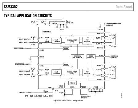
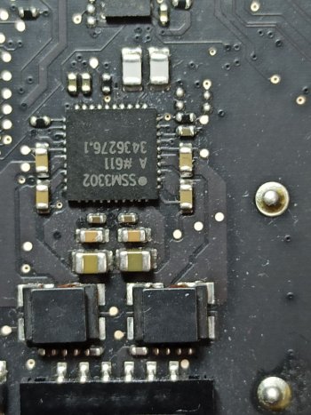
Well On the motherboard of my imac A1419 2015 later it has the SSM3302IC, a one for each channel. This IC is a Dual Channel power amplifier 10wx2 in Class D. On board i Only see a two inductances associated with ClassD, but don't included passive crossover, i imagine that the design is a Active Crossover.
i am not able to find the board schematic or detailed data.
My JRY included a IC PAM8003 is a IC ClassD but only 2.5w each channel, i had abaout remplacing it with the IC PAM8004, but is low power too, other option is to extract the input signal from PAM and take it to external module classD 2x10 or 2x15w, but the ic 8003 need a pin 12 to volume control, pffff i Only other option.....if possible to using the headphone output jack. I think it will stay with the onli 2.5w for channel
Attachments
Last edited:
@Xarl-li When you have control over the whole audio signal chain it's far easier to do crossover correction at the start of the amplification path.
Interestingly, the 2015 iMac has an analogue signal path, with as you say one amplifier for each side of the iMac.
From the 2017 iMacs, the signal path remains digital and there are four digital amplifiers, one for each speaker driver unit, two per side.
So the digital signal correction for each driver is even more controllable and no crossover units are required.
At least the PAM8003 amp in the JRY--AA1 is specified for 4/5 ohms so is well matched to the 4 ohm iMac speakers.
The R1811/R9A18 CSC3110 audio amp is specified for 8 ohms, so isn't a perfect match.
However the digital amps Apple used after 2017 were also specified for 8 ohms, and obviously they work fine with 4 ohm driver units...
Last edited:
@Xarl-li You should be able to use an external amplifier connected to the headphone jack in case the onboard one is not strong enough. Just check with headphones that you can control the volume there as well from your keyboard.
Would've done it too if the amp on my board was not up for the task.
Would've done it too if the amp on my board was not up for the task.
Register on MacRumors! This sidebar will go away, and you'll see fewer ads.