Become a MacRumors Supporter for $50/year with no ads, ability to filter front page stories, and private forums.

arw

macrumors 65816
Aug 31, 2010
1,227
974
Any recommendations regarding optimum color settings?
Like would the Dell UltraSharp Calibration Solution work?
Thanks!

LG LM270QQ1 SDA1 with R9A18
Dual DP from Mac Pro 2013 D300 on Big Sur
Identified as DELL UP2715K @5K 30-Bit Color (ARGB2101010)

On a sidenote, my controller board would not save its settings after disconnecting power.
Flashing R9A18_V01_LM270QQ1_5120x2880_edp_8Lane.bin fixed it.
 
Last edited:

yaosiang

macrumors member
Jul 3, 2010
57
47
Any recommendations regarding optimum color settings?
Like would the Dell UltraSharp Calibration Solution work?
Thanks!

LG LM270QQ1 SDA1 with R9A18
Dual DP from Mac Pro 2013 D300 on Big Sur
Identified as DELL UP2715K @5K 30-Bit Color (ARGB2101010)

On a sidenote, my controller board would not save its settings after disconnecting power.
Flashing R9A18_V01_LM270QQ1_5120x2880_edp_8Lane.bin fixed it.
I find the colour of the default colour profile for DELL UP2715K pretty flat (not as vibrant) so I suggest you try something different.

On the R1811, the monitor is recognised as X27 Pro on macOS and the colour looks very vibrant. In fact, it might be slightly oversaturated. I use it with the R9A18 and it looks better than the default colour profile.
 
  • Like
Reactions: arw

arw

macrumors 65816
Aug 31, 2010
1,227
974
I find the colour of the default colour profile for DELL UP2715K pretty flat (not as vibrant) so I suggest you try something different.

On the R1811, the monitor is recognised as X27 Pro on macOS and the colour looks very vibrant. In fact, it might be slightly oversaturated. I use it with the R9A18 and it looks better than the default colour profile.
Thanks. Yes, the default one is of no real use. I had hoped to find recommended "looks like iMac" settings but I think I'm getting close to a natural yet stunning state.
 

citivolus

macrumors 65816
Sep 19, 2008
1,217
268
@fiatlux what’s the version number of your R1811 board’s firmware? Are you looking to drive a 5K display with a single DP cable?
 

Gold240sx

macrumors newbie
Jan 15, 2021
7
6
My Ultimate 5K Build is Finally Complete!
(Previous earlier part of this build Is earlier in this post. I've made a few changes in terms of direction)

Summary:
  • Video and Audio running through usb-c.
  • 1TB of internal NVME SSD storage attached.
  • I have a secondary Bluetooth audio input to the speaker system.
  • Working 8 speaker setup including the OEM iMac speakers.
  • Additional HDMI in and a dual Display Port => usb adapter
  • Microphone w/ audio input.
  • Front facing Control board.

IMG_0638.JPEG


!!!——— I’ll also go into how I got the both my monitor and iMac speakers working simultaneously w/ software with working vol +, vol-, and mute for both screens———!!! Removable cable. Lol
I’ll include all the parts that were eventually used - at the bottom here if you wanna build the same.


My final Take:

I could have gone with a bit more power for the amp / audio inverter for the speakers (even with only the iMac speakers). They do drive at 2/3 the volume of the iMac at high volume but at much more distinct bass/ mid/ + highs. I rarely blast my speakers but I wanted something close to equal sound quality wise, and I’m very happy with the sound output for what I use a computer for. I’m not trying to host a party with my iMac speaker, but it’s plenty loud for a single person or a few people watching a movie. Video works great and as expected with one large caveat. Trying to replicate HDR brightness to match my iMac's screen seems impossible. I think that's just because (correct me if i'm wrong) that other than the 6K XDR, apple doesn't drive alternate monitors to receive HDR. So the closest setting(I usually have my monitors at full brightness whenever on, the whites on the DIY monitor seem a bit washed out in comparison, to a point where I. actually can't see very light grey on the DIY display, vs the iMac's where you can easily see everything. A Big difference! It just came to a point that to do color correcting etc, to keep it on my iMac screen, whereas apps like Microsoft word where its mainly grey/black and white with lots of contrast live on the monitor.Dispite this, it was fun building this, I'm happy with the (what I feel) very successful builds and the most complicated project I've done, and in addition to this a great monitor that I can show off, use in the future and brag about to my friends. And it still cost $700-$1000 less than a purchase of the new Studio Display, which has HDR, but 4 speakers (instead of 8), different design, and no removable power cable or Bluetooth or built in, and isn't an exact replica of the computer your pairing it with!


IMG_1407 2.jpg


thermal temp.jpg


temp closeup.jpg


IMG_1434.jpg


IMG_1431.jpg


Few things I learned - lessons to share (by category):


Power:


Usb-powered NVME drives work perfectly plugged into the driver board. Buy any of those portable NVME enclosures to USB adapters.

power wiring.jpg


—————

Driver Board, and Temperature Control + Heat:

I can confirm after 8 months of using the driver board without a fan, it hasn’t overheat or shut down at all (with 1 inverter). Since most of you aren’t going to have 3 separate inverters like my final setup, I’m pretty comfortable recommending just taking the fan out. With these 3 inverters now, just to be safe I purchased a 12V Noctua 80mm fan to plug into the 12V amplifier power ports. (Uses .84W) of power so it shouldn’t decrease audio output by any recognizable amount. After wiring up the fan, I very quickly became quite uncomfortable with he noise level, even with the quiet wire than decreases the fan speed. (I like a silent / near silent computer. At the same time though, I did want the computer to cool down when (and only when) the temps became a little too hot for comfort. While I don’t think it’ll hit temps like that, Its nice to have the option for a backup. This is where the temperature controller came in. (LED) in the right hand corner. This thing was a pain in the *** to setup. In case you decide to include one in your build, wiring (from left) is +(fan wire), +12vPower input, +12vbridgedPowerInput, and -Power input. Setup videos are available on YouTube. A lot of people online shorted these boards out. (I shorted 2 of them and had to wait for another order. 3rd time was the charm. The shorts came from installing the screws from the back (instead of the front) or from the wiring being so close together. This was fixed with a bit of soldiering so only 1 wire went into any terminal. I set the thermostat to turn the fan on at 180º F / 82.2ºC. So far the fan has yet to come on. Temps with the screen perched against the case (after an hour) ran up to the mid 30ºC range with my apartment being at 74ºF. (pic provided). I did remove the screen after 5 hours of use to see what temps the thermostat was picking up inside, and it looks like the average internal ambient temp was sitting at about: 39.6ºC (103ºF). The screenful maybe 10 or 15 degrees hotter. Because of the (still very large (~70ºC) temp gap, I moved the temp sensor to above the fan and below the main inverter mounted to the display, since that's the most expensive part of all of this. Then I took the back-of-the-display temperature (unmounted to the chassis but running) read at around 44ºC (111ºF).

spinny fan.jpg


—————

iMac speakers:

(original amps- Replaced):
RenderedImage.jpg

Initially I tried driving the iMac speakers with the 5v 2A PSP inverter.(product No. below) coupled with (2x) 5w + 5w amplifiers. (One right one left). While I was able to hear it (barely) the power was horrendous and far from what you’d expect from iMac speakers. Both the amps and power adapter were replaced / used for something else.

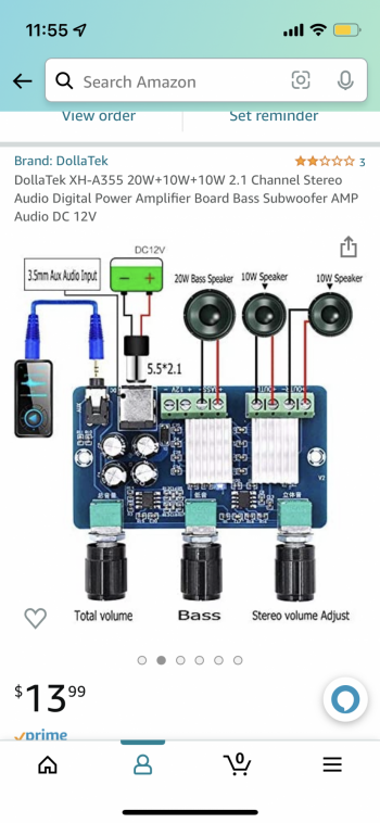
You’ll see 6 wires coming off of the iMac speaker connector. Clip the connector off. You’ll need to extend the length of the wire with some random wire you have around ( you can use the Stonetech speaker wire if you purchased). Roll back the sheathing. 2 of the connectors are not in use, leaving you with only sub+, sub-, tweet+,tweet- per speaker. To find which ones which I just connected them to the 10W amp. It was pretty clear which one was which. Subs were connected to the 20W output.Tweets to the 10W. The secondary speakers were also connected to the 10W. They sounded really nice connected to the 10W’s as mids. iMac and secondary Speakers were eventually powered by a 12V 5A 60W inverter, coupled with a 20W+10W+10W 12V amplifier. The 4 pin audio out on the driver board didn’t end up working, it was much easier just connecting the aux cable to the audio jack.


—————

Audio setup:

I connected the amplifier to a Y splitter M => FF aux cable. The females connected to the aux cable coming straight from the driver board and 1 cable connected to the bluetooth audio out.

amp diagram.PNG


—————

Bluetooth:

The 5W power supply I previously used for the 2 5W amps, ended up being used to power the Bluetooth adapter. (Saves a USB port on the driver board since it can be powered via microUSB alternatively) Because the driver board 4 pin wasn’t outputting audio, my initial plan was to send audio via bluetooth. This worked well until I played music and the music via bluetooth had about a 3/4 second delay. I kept the Audi output since I thought it would be cool to keep the Bluetooth for devices other than my iMac. Something pretty cool I learned is that of course bluetooth doesn’t transfer through I iMac case / screen, but the OEM wifi/bluetooth antennas (already routed around the perimeter PERFECTLY connect to the bluetooth adapter allowing the bluetooth to work! When I upgraded my iMac, the one thing that doesn’t work is my microphone hasn’t worked since, so I plugged in a 3.5mm microphone into the bluetooth adapter, using this as my computers main microphone.

temp closeup.jpg


—————

Software and multi-audio-output Setup:

To get both the iMac and monitor’s speakers to work simultaneously, go to Applications > Utilities > Audio Midi Setup. Hit the + and select both the internal and X27 Pro as output. Now audio should work, but you won’t have any control over the volume or volume buttons. I guess there are alternatives but the quick and easy way I used is a program called Sound control. It was $27 after tax, and makes everything work flawlessly. You can install it as a 14-day trial. For me though the volume keys didn’t work until I had purchased. I was also able to set the bluetooth’s microphone as the system’s main microphone through this app. This made it VERY Easy.

sound control.jpg


—————

Data Transfer:

Data transfer rates to anything plugged into the driver board’s USB port while outputting 5K and audio through the USB port, is limited to about 35MB / sec as opposed to the same drive and cord plugged directly into the iMac receiving 435MB/sec USB3.1 - 535MB/Sec(usbC). So while the integration and access to your data at all times is cool, you do suffer a major transfer speed penalty, along with losing the benefit of portability and a potentially decreased lifespan being in hotter than ambient temperatures.. The only gain here is that it uses one less USB/C port.

IMG_1429.jpg


Parts List eventually used:

-r1811 display board (usb-c)
-2019 display
-unknown year (2016-2021) tapered iMac case
-tapered OEM iMac speakers
-PSP charger: https://www.amazon.com/dp/B097MZV8MS/ref=cm_sw_r_cp_api_i_E5D87ZEBY9MW7640FGJ7?_encoding=UTF8&psc=1
-20w, 10w, 10w Amplifier: DollaTek XH-A355 20W+10W+10W 2.1 Channel Stereo Audio Digital Power Amplifier Board Bass Subwoofer AMP Audio DC 12V https://www.amazon.com/dp/B08HQW6MJ8/ref=cm_sw_r_cp_api_i_G0SGR6B9RJJ9N1FMNJCE?_encoding=UTF8&psc=1
-Bluetooth Board: Blue~Tooth Board, DROK 12V Audio Receiver Blue~Tooth Module DC 5V-12V Portable Wire~Less Electronics Stereo Music Receive Circuit Chip with Micro USB Port for Headphone Speaker Home Sound System DIY https://www.amazon.com/dp/B07P94Z9XR/ref=cm_sw_r_cp_api_i_9KPJTYXAWQ97XW3BNCJW?_encoding=UTF8&psc=1
-Y Aux Splitter: StarTech.com 6 in. 3.5mm Audio Splitter Cable - Stereo Splitter Cable - Gold Terminals - 3.5mm Male to 2x 3.5mm Female - Headphone Splitter (MUY1MFF),Black https://www.amazon.com/dp/B0000DIESU/ref=cm_sw_r_cp_api_i_K5M9Y6VNJC5QC387KVDV
-Dual DP to thunderbolt adapter (OWC Thunderbolt 3 Dual DisplayPort Adapter (OWCTB3ADP2DP)) - https://www.zoro.com/owc-thunderbolt-3-dual-display-owctb3adp2dp/i/G7590356/?utm_source=google&utm_medium=surfaces&utm_campaign=shopping feed&utm_content=free google shopping clicks
-StoneTaskin High quality Audio speaker for R9513 R9516 R9A18 R1811 Panel 5K Driver Board Speaker 8 ohm 10W 100% Tested https://a.aliexpress.com/_mK0OFJc
-FingerLakes 3.5mm Microphone Assembly Mic for Car Vehicle Head Unit Bluetooth Enabled Stereo Radio GPS DVD https://www.amazon.com/dp/B015KY5J7Y/ref=cm_sw_r_cp_api_i_5EBSHB1GBVEH7M2T56XG
-SanDisk 4TB Extreme Portable SSD - Up to 1050MB/s - USB-C, USB 3.2 Gen 2 - External Solid State Drive - SDSSDE61-4T00-G25 https://www.amazon.com/dp/B08RX4QKXS/ref=cm_sw_r_cp_api_i_5JSK5VSEAVR4AZR6HCRW
-Noctua NF-A8 PWM, Premium Quiet Fan, 4-Pin (80mm, Brown) https://www.amazon.com/dp/B00NEMG62M/ref=cm_sw_r_cp_api_i_TW14RS8YFA2YJ56K16NQ
-M.2 NVMe SSD Enclosure Adapter, Unitek Aluminum USB 3.1 Gen 2 10Gbps to NVMe PCIe M-Key Solid State Drive External Enclosure Support UASP & Trim Compatible for M.2 M-Key SSD 2230/2242/2260/2280 https://www.amazon.com/dp/B08BBY1FXJ/ref=cm_sw_r_cp_api_i_425GMS03XTD2Y0G9M9QD
-(2x) 8K 1” DP cables: (purchased at Microcenter)
-old 1TB OWC NVME drive from my 2011 MacBook Air
-Songhe XH-W1209 W1209 DC 12V Digital Temperature Controller Board Module Digital Thermostat Temperature Control Switch -50-110°C with Waterproof (3PCS) https://www.amazon.com/gp/product/B07YZSPXGX/ref=ppx_yo_dt_b_asin_title_o00_s00?ie=UTF8&psc=1
-Aux Cable.


Parts purchased, not used:

  • 2 Pieces Audio Amplifier Board Pam8406 Mini Amplifier Board Dc 5v, 5w+5w Amplifier Module, Digital Power Module Class D 2.0 Dual Channel Audio Stereo Amplify Board for DIY Sound System https://www.amazon.com/dp/B08RDN58SZ/ref=cm_sw_r_cp_api_i_ZE8QJ7DNZT33MBVN791W?_encoding=UTF8&psc=1
  • comp4TB Sandisk NVME. ( obviously I ended up using this but the data transfer speeds connected to the display board ( and stored internally) made it too much of a drawback to keep inside the display.) I felt much more comfortable keeping that as an external portable drive and leaving that 1TB iMac drive internally. The only drawback is that it uses an additional USB/USBC port.

speaker test.jpg


4pin speakers.jpg


screen seperate.jpg


Earlier in the build:
993886-64466bec16414ebc542ed6234e6f0495.jpg.png

993884-1754f3522140249a7c58a7bcabec5b3b.jpg.png


Hope this helps or inspires other in their build! Feel free to ask whatever questions you may have!

Wiring diagram(single line)

Screen Shot 2022-04-18 at 1.06.20 AM.png


**VIDEO ** Sound Comoparison between iMac only VS Multi-Channel Audio ( both Displays: 12 total internal speakers ):


Attachments

  • amp diagram.PNG
    amp diagram.PNG
    1.2 MB · Views: 348
Last edited:

PaulD-UK

macrumors 6502a
Oct 23, 2009
866
465
Quote: Gold240sx
"The 4 pin audio out on the driver board didn’t end up working, it was much easier just connecting the aux cable to the audio jack."

What happened there?
Does the bluetooth card function OK without access to controls (when the screen is in place)?

Nice build, nice pix. Thank you.
 

jgv115

macrumors newbie
Oct 18, 2021
2
3
Hey everyone, really interesting thread!

I stumbled across this video:

In this video it seemed like a R9A18 board was used and it seemed like it supported DP1.4 and only a one cable connection for 5k resolution.

Based on what I'm reading in this thread, it seemed like in the past this board could only drive 5k with 2 DP1.2 links. Has there been an update to the board or something like that?
 
  • Like
Reactions: Marty_Macfly

PaulD-UK

macrumors 6502a
Oct 23, 2009
866
465
R9A18 V1: Only supports DP1.2

R9A18 V2 V1.1: Supports DP1.4 DP1.3

R1811 V3 + V4: Supports DP1.4 and USB-C.

From the German language equivalent of this thread:
 
Last edited:

joevt

macrumors 604
Jun 21, 2012
6,935
4,237
R9A18 V1: Only supports DP1.2

R9A18 V2: Support DP1.4

R1811 V3 + V4: Supports DP1.4 and USB-C.

From the German language equivalent of this thread:
Do any of them support DSC?
 

cabal2000

macrumors newbie
Feb 17, 2013
9
0
So, this is very new to me. I am running a Hackintosh with a Radeon RX 580 4 GB. But planning on a Studio Mini in the near future. Which is the better board? I see that there are 2 different ones and now I am confused on which one to get..
 

davidg5678

macrumors regular
Dec 5, 2020
128
108
So, this is very new to me. I am running a Hackintosh with a Radeon RX 580 4 GB. But planning on a Studio Mini in the near future. Which is the better board? I see that there are 2 different ones and now I am confused on which one to get..
My understanding is that the R1811 is the better/newer board, but it costs more. The older revisions are a bit less expensive and work well, but among other small differences, they happen to lack the same USB-C connection functionality (without additional adapters.) The German thread linked above (I used Google Translate to read it) has a lot of information about the different board revisions if you'd like more details. It seems to me that the R1811 board can only be ordered from AliExpress, but some of the other revisions are available elsewhere online.
 
  • Like
Reactions: cabal2000

cabal2000

macrumors newbie
Feb 17, 2013
9
0
-Looking for a link to a good seller of the R1811 boards.
-Anyone have a pinout for the R1811 v4 boards?
-anyone using the apple speakers that are in the A1419?
 

davidg5678

macrumors regular
Dec 5, 2020
128
108
-anyone using the apple speakers that are in the A1419?
If you search this thread, there are several people that have managed to reuse the speakers with good working results. See here: https://forums.macrumors.com/threads/diy-5k-monitor-success.2253100/post-31031196

In my personal opinion, at least from an audio quality perspective, it is probably not worth the extra cost/effort to add an amplifier and connect the stock internal speakers. It's possible that for roughly the same amount of money/work (if not less,) connecting some used bookshelf speakers and the same ~$20 Class D amplifier could sound significantly better. Of course, this is just a matter of opinion, and whatever you do is completely up to you. :)

There are a few pinouts/wiring diagrams scattered throughout this thread if you do a quick search through the pages. This aliexpress page also has a diagram that is useful too:
1652137685888.png
 
  • Love
Reactions: cabal2000

ikiwi84

macrumors newbie
Apr 18, 2015
3
1
Well I've finally completed my build based on the R1811 LCD driver board. I followed the guidance in this thread and others but also put my own spin on it. I was concerned about installing every component in the iMac case including the driver board power supply. I thought heat build-up could be an issue with the power supply in the case. I have had similar power supplies fail in the past so I thought it's possible it may need to be replaced in a year or so. Lastly I wanted access to the driver board to easily plug in devices and also potentially upgrade the driver board in the future. I have no desire to open up the iMac again once it is sealed so mounting these externally was key.

The length of the LCD driver board cable was a determining factor. Based on its length, I realized I could mount the board externally, but not too far away. I came up with a plan to house the board in a small break-out box and attach it to the iMac stand. I found a mini-ATX case that matches the industrial metal look of the iMac and like how it turned out.

I planned to use the 5K monitor with my new Mac mini so a webcam was necessary. I hate the look of a webcam propped up on top of the monitor, so ideally I wanted to install a camera in the case similar to the iMac. I knew that the FaceTime camera from iMacs prior to 2012 as well as the Thunderbolt Display could be converted to USB; however, I found that space at the top of the thin iMac case was very challenging. This was the hardest part of the build for me. Ultimately I was able to disassemble a FaceTime camera board from a Thunderbolt Display to make it as small as possible, hook up a usb cable to it, and get it to fit (extremely snugly) within the iMac case. Overall I am very happy with the result.

During my research I read about people replacing the LCD screens on iMacs, only to have them come apart and crash to the floor at some point. To address this, I installed a series of zip-ties with adhesive mounts to catch the LCD as emergency straps just in case it separated from the iMac case.

I also replaced the LCD driver board fan with the Noctua fan recommended by @Borzab to make it an almost silent device. I didn't like the PCB board supplied with the R1811, so I installed a new LED at the top of the case and a new IR receiver on the bottom of the case to receive signals from the included remote control.

While I had the opportunity, I also went ahead and replaced the original plastic hinge washers with metal ones I found eBay to preemptively address the infamous "broken hinge" problem plaguing some iMacs.

Thanks to everyone for posting their experiences in this thread—it has been a really fun and useful project!

Below are some pics of my build...
@citivolus, I know this has been quite a while since you posted this. However, would you mind sharing a few more details about integrating the webcam module from the thunderbolt display?
What did you have to modify to make this work? Any changes on the chassis of the iMac?
Does the microphone work as well?
What resolution does the camera have? Is it comparable to the iMac camera?
Is there any other camera that would fit?
Youtuber Luke Miani has used this camera module. However, I would prefer something with a microphone unit included.
 

citivolus

macrumors 65816
Sep 19, 2008
1,217
268
@citivolus, I know this has been quite a while since you posted this. However, would you mind sharing a few more details about integrating the webcam module from the thunderbolt display?
What did you have to modify to make this work? Any changes on the chassis of the iMac?
Does the microphone work as well?
What resolution does the camera have? Is it comparable to the iMac camera?
Is there any other camera that would fit?
Youtuber Luke Miani has used this camera module. However, I would prefer something with a microphone unit included.
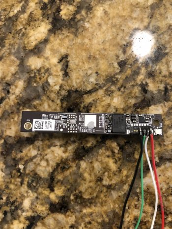
Sure, this was a really fun project. The camera I used is the Apple Camera Cable for 27" Thunderbolt Display Apple Model #: 922-9934. I removed the extra housing and other unnecessary plastic pieces to get at just the actual pcb camera module. I also removed the pins for the connector as they were preventing the module from fitting into the case properly. I then soldered the appropriate USB cables from the end of a spare USB cable to the contacts on the pcb directly using the original connector camera cable as a reference:

USB Ground -> Camera black
USB Power (red) -> Camera orange
USB Green -> Camera yellow
USB White -> Camera blue

When mounting the camera pcb board in the case, I also had to use a dremel to trim away some of the black plastic supporting trim on the inside of the case to get it to fit. I then used hot glue to secure the board within the case and fed the usb cable through the hole I had cut in the back of the case. Pointing it slightly downward to get it to appropriately show the picture was a challenge and took many tries!

macOS Monterey sees the camera as:

FaceTime HD Camera (Display):
Model ID: UVC Camera VendorID_1452 ProductID_4370
Unique ID: 0x220000005ac1112

I believe the resolution is 720p and is actually better than my old iMac 2009 integrated camera. I wanted to use an Apple integrated camera to ensure compatibility with built-in drivers in macOS going forward. Not sure if there is an integrated microphone but I am just using the camera for video.

For a microphone, I took an old iPhone 3.5mm headset with integrated microphone, cut off the headphones and plugged it into the headset jack on the back of my M1 Mac Mini. I glued the small microphone at the bottom of the monitor to keep it out of sight. In the macOS Sound->Input Preferences app, I chose the option “External Microphone”. In FaceTime I chose the option “Use System Setting” Under the “Video->Microphone” menu.

Regarding Youtuber Luke Miani, I watched his video and he didn’t use an integrated iMac camera module (despite the Macrumors article saying so). In his video you can see that he instead used this Android camera which seems to physically fit well, but according to reviews on Amazon, the fps and lighting may have some issues.

Attached are a few pictures. Feel free to ask anything else and I will try to help out.
 

Attachments

  • 52131209-D91C-4F37-A307-CCAF4527A0C9.jpeg
    52131209-D91C-4F37-A307-CCAF4527A0C9.jpeg
    116.9 KB · Views: 249
  • img_5854.jpeg
    img_5854.jpeg
    525.4 KB · Views: 244

usb3

macrumors newbie
Nov 23, 2020
23
13
Is there any way to determine if you have a LM270QQ1 or LM270QQ2 before opening the iMac?
 

PaulD-UK

macrumors 6502a
Oct 23, 2009
866
465
As I understand it, all 27" 5K iMacs have LM270QQ1 screens.
LM270QQ2 panels don't have the bonded glass fronts, and are used by LG in their own 27" 5K monitors.
 
  • Like
Reactions: usb3

yashka

macrumors newbie
May 16, 2022
6
0
So I too built one of these... using the R9A18 v1 board. It worked "okay", but unfortunately, it was immediately clear that the backlight driver (30W) could not supply enough power to get the screen to full brightness (Based on the LM270QQ1 datasheet looks like around 36-38 W). I didn't want to get a new driver board and wait another month and sink more money into this, so I did something stupid, and I'm pretty sure I "exploded" either my driver board, my LED backlight, or both.

I hooked up a constant current 650 mA LED driver in parallel to the existing LED driver. It actually worked for a while, but I kept "messing" with it, and maybe nuked the R9A18 LED power circuit. Or I nuked the backlight. I'm not sure which, honestly. The driver board is still putting out 12V on the backlight power cable. Constant current driver at 12 V / 1 A won't light the backlight.

Any ideas on how I could figure out what I broke? I don't have access to another screen and at this point probably won't spend yet more money to dig myself out of this hole, unless the panel/backlight is undamaged.
 

citivolus

macrumors 65816
Sep 19, 2008
1,217
268
So I too built one of these... using the R9A18 v1 board. It worked "okay", but unfortunately, it was immediately clear that the backlight driver (30W) could not supply enough power to get the screen to full brightness (Based on the LM270QQ1 datasheet looks like around 36-38 W). I didn't want to get a new driver board and wait another month and sink more money into this, so I did something stupid, and I'm pretty sure I "exploded" either my driver board, my LED backlight, or both.

I hooked up a constant current 650 mA LED driver in parallel to the existing LED driver. It actually worked for a while, but I kept "messing" with it, and maybe nuked the R9A18 LED power circuit. Or I nuked the backlight. I'm not sure which, honestly. The driver board is still putting out 12V on the backlight power cable. Constant current driver at 12 V / 1 A won't light the backlight.

Any ideas on how I could figure out what I broke? I don't have access to another screen and at this point probably won't spend yet more money to dig myself out of this hole, unless the panel/backlight is undamaged.
I think you need one of these “constant current” add on boards for your R9A18 to address the brightness issue:


SlightWince

macrumors newbie
Feb 25, 2022
27
39
So I too built one of these... using the R9A18 v1 board. It worked "okay", but unfortunately, it was immediately clear that the backlight driver (30W) could not supply enough power to get the screen to full brightness (Based on the LM270QQ1 datasheet looks like around 36-38 W). I didn't want to get a new driver board and wait another month and sink more money into this, so I did something stupid, and I'm pretty sure I "exploded" either my driver board, my LED backlight, or both.

I hooked up a constant current 650 mA LED driver in parallel to the existing LED driver. It actually worked for a while, but I kept "messing" with it, and maybe nuked the R9A18 LED power circuit. Or I nuked the backlight. I'm not sure which, honestly. The driver board is still putting out 12V on the backlight power cable. Constant current driver at 12 V / 1 A won't light the backlight.

Any ideas on how I could figure out what I broke? I don't have access to another screen and at this point probably won't spend yet more money to dig myself out of this hole, unless the panel/backlight is undamaged.
I'm in the process of trying all of this out with a late 2015 iMac display and a R9A18 V1 board (still waiting for the driver board to arrive). Just curious, which iMac display were you using? So the constant current board worked to get the display in reaching full brightness? What "messing" with it did you do? Also, do you have a link to the constant current board that you purchased?
 

yashka

macrumors newbie
May 16, 2022
6
0
LM270QQ1-SDA2 (2014) display. I used this LED driver - https://www.tinyosshop.com/index.php?route=product/product&product_id=749 definitely don't recommend you follow in my footsteps as I caused magic smoke to come out of my R9A18 doing electrically improper things. These things really aren't intended to be run in parallel with other current regulated connections, I found out. At least the LED backlight still seems to work at low brightness, so I don't think I completely toasted the monitor.


Also, I made the probably completely incorrect assumption that the backlight power was just a constant DC 12 V with regulated current. No idea if that is true and it's completely possible that it needs to be modulated in some way that I don't understand.
 

eicca

Suspended
Oct 23, 2014
1,773
3,604
This would be VERY cool to do with one of the OG 27" LED Cinema Displays.
 
Register on MacRumors! This sidebar will go away, and you'll see fewer ads.