What resolution are you working at in 5K?In a previous post I mentioned problems with eye strain with JRY-W9QUHD-SA1 and iMac 2017 panel driven by USB-C. At first I thought it was related to dithering caused by 10 bit color (8 bit + frc). Even though I disabled dithering with Still Color and forced 8 bit color mode with Better Display my eyes had problem focusing and I got headache.
Since I previously used an iMac 5K late 2014 8 hours a day for many years without issues I thought the SA1 board maybe was the issue. Some how I started looking into the bandwidth needed to drive 5k with the help of https://trychen.com/feature/video-bandwidth and saw that in order to drive the monitor with DisplayPort Alt Mode on USB-C I where forced to use DSC (Display Stream Compression) and thought maybe DSC was causing my issues. Therefore I instead tested with DisplayPort 1.4 (HBR3) and forced colors to 8 bit (since 10 bit is not supported on DP 1.4 without DSC) and to my surprise I have been able to work the whole day without issues. It is also possible to use HDMI 2.1 even with 10 bit color mode with the JRY-W9QUHD-SA1 without the use of DSC.
Since I mostly use my monitor with text (coding) and since 10 bit requires dithering I would not bother with 10 bit but instead make sure it is possible to drive the monitor without DSC. Related to JRY—AA1 I can not tell from the specification if it uses Display Port 1.3 or later or not. If it has Display Port 1.3 (HBR3) I would personally be fine using it instead of SA1. Now I understand why the Studio Display and Ultra Fine uses Thunderbolt, since that way they can provide the necessary bandwidth to drive the monitor at 10 bit without DSC and also have extra bandwidth for USB-hubs, cameras & microphones.
I tried to read about the effects of DSC online but could not find much information. From what I understand DSC is not commonly used.
Got a tip for us?
Let us know
Become a MacRumors Supporter for $50/year with no ads, ability to filter front page stories, and private forums.
DIY 5k Monitor - success :-)
- Thread starter fiatlux
- WikiPost WikiPost
- Start date
- Sort by reaction score
You are using an out of date browser. It may not display this or other websites correctly.
You should upgrade or use an alternative browser.
You should upgrade or use an alternative browser.
- Status
- The first post of this thread is a WikiPost and can be edited by anyone with the appropiate permissions. Your edits will be public.
"You can get away with just a 0.15 milliHenry air-core inductor in series with the woofer, and a 10 microFarad audio-grade capacitor in series with the tweeter."@Bassy_92 "...will the 3watts of power be sufficient with the OG 1419 speakers?"
Yes, the internal amp on the board is designed for 4 ohm speakers, like the iMac's, and will be as good as the cheaper recently introduced Asus and Provision 5K monitors.
Not as good as a Mac, but usable.
Don't overbuy the crossovers, as the ones being sold on AliE are not specced right for the iMac's speakers...
I've posted about it earlier, and done an analysis of the original AliE one, which has an iron-cored inductor.
You can get away with just a 0.15 milliHenry air-core inductor in series with the woofer, and a 10 microFarad audio-grade capacitor in series with the tweeter.
this is the part that seems way over my head and I dont really know what im doing... but what I have managed to do is reuse the aux port for a seamless audio output to my desk speakers via 3.5 jack.
tested and works a treat so will perhaps leave the internal speaker out for the v1.0 build.
mainly due to great audio wasn't on my list of objectives for this project so im okay with this solution...
waiting for the rest of the bits to arrive in the post before I do a proper testing
Attachments
I am using HiDPI 2560x1440 since it is the sharpest option.What resolution are you working at in 5K?
Did I understand you correctly that DSC doesn’t work at all at this resolution?I am using HiDPI 2560x1440 since it is the sharpest option.
@yurazazik With a R1811 using a USB-C to DP1.4 cable and an M4 Pro mini, using DSC I get 10 bit Full RGB, but if I turn off DSC then the colour mode drops to 8 bit Full RGB.
So running HiDPI 2560x1440 without DSC disables the display stream compression, and as it works at 8 bit it also disables FRC ( the Frame Rate Conversion) flicker which allows the panel to display a 10 bit image.
With Better Display it is possible to run at 10 bits with DSC-Off but the colour space drops to Limited Range YCbCr 4.2.2, which is fine for viewing video, but lowers the colour resolution for still image work.
It is highly likely that the JRY--SA1 works in this way.
Last edited:
@PaulD-UK The JRY—SA1 behave in the same way those resolution and color options can be used without DSC but the only way I know that is by calculating needed bandwidth. Mind I ask you how you are able to disable DSC? Is it an option in BetterDisplay or something you can do in the on screen menus of the R1811? The SA1 has no option to disable DSC in the menus.
@yurazazik DSC works and makes the full 5K resolution in 60Hz with 10 bit RGB available and everything looks perfect to the naked eye but I personally can not use it comfortably for any longer period of time. If I use USB-C to DisplayPort and turn down color depth to 8-bit (to prevent the use of DSC) I can use the monitor comfortably for prolonged time.
@yurazazik DSC works and makes the full 5K resolution in 60Hz with 10 bit RGB available and everything looks perfect to the naked eye but I personally can not use it comfortably for any longer period of time. If I use USB-C to DisplayPort and turn down color depth to 8-bit (to prevent the use of DSC) I can use the monitor comfortably for prolonged time.
Last edited:
@yurazazik With the R1811 board the DSC switch is in the OSD Advance Menu Option.
With the older V04 firmware it is the last option at the bottom of the page.
With the new Blue OSD version DSC is on the 2nd page of the Advance options, so you have to scroll down to the 2nd page where it's the 3rd choice.
You do need Better Display to see what effect it is having.
With the older V04 firmware it is the last option at the bottom of the page.
With the new Blue OSD version DSC is on the 2nd page of the Advance options, so you have to scroll down to the 2nd page where it's the 3rd choice.
You do need Better Display to see what effect it is having.
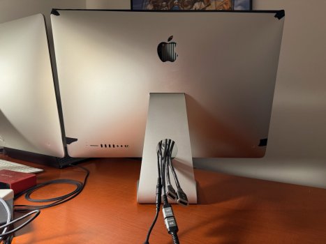
Time to share an update the final form of my simple FA1 5K conversion!
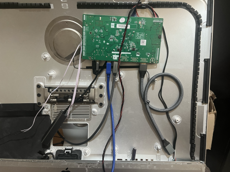
I popped out the logo from the back, mounted the board FA1 at the top of the case, and the heat sink pumps hot air right out the opening. Working on a 3d printed insert with slats which will slip in the opening.
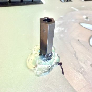
The board is mounted on nylon standoffs which were affixed to the case. Roughed the smooth case, cleaned with IPA, hot glued down.
DP & HDMI female extensions run out the RAM slot. Zip tied the cables to the case via 3M adhesives for tension relief.
A 5 position joystick to control the board has access out the Ethernet port. It's sandwiched between the case and some foam.
I avoided new adhesive on the screen by using black painters tape instead. It's easy to remove and get back in if I need and much more pleasing than the blue tape!
Parts list comes in under $500:
• 5K Late 2015 • $150 FB Marketplace
• JRY-W9RQUHD-FA1 • $168 Stone Taskin
• HDMI 8K Extension (2) • $26 Amazon
• DP 8K Extension (2) • $10 Amazon
• USB-C to DP Cable (2) • $23 Amazon
• SHNITPWR 24V 8A External Power Supply • $30 Amazon
• 5 Direction Navigation Module (5-pack) • $9 Amazon
• 3.5mm Audio Extension • $6 Amazon
• 2" Kapton Tape • $13 Amazon
• 1" x 20 yards black painters tape • $7 Amazon
• M3 Nylon Hex Spacers • $10 Amazon
I popped out the logo from the back, mounted the board FA1 at the top of the case, and the heat sink pumps hot air right out the opening. Working on a 3d printed insert with slats which will slip in the opening.
The board is mounted on nylon standoffs which were affixed to the case. Roughed the smooth case, cleaned with IPA, hot glued down.
DP & HDMI female extensions run out the RAM slot. Zip tied the cables to the case via 3M adhesives for tension relief.
A 5 position joystick to control the board has access out the Ethernet port. It's sandwiched between the case and some foam.
I avoided new adhesive on the screen by using black painters tape instead. It's easy to remove and get back in if I need and much more pleasing than the blue tape!
Parts list comes in under $500:
• 5K Late 2015 • $150 FB Marketplace
• JRY-W9RQUHD-FA1 • $168 Stone Taskin
• HDMI 8K Extension (2) • $26 Amazon
• DP 8K Extension (2) • $10 Amazon
• USB-C to DP Cable (2) • $23 Amazon
• SHNITPWR 24V 8A External Power Supply • $30 Amazon
• 5 Direction Navigation Module (5-pack) • $9 Amazon
• 3.5mm Audio Extension • $6 Amazon
• 2" Kapton Tape • $13 Amazon
• 1" x 20 yards black painters tape • $7 Amazon
• M3 Nylon Hex Spacers • $10 Amazon
Attachments
As an Amazon Associate, MacRumors earns a commission from qualifying purchases made through links in this post.
Just in case anyone is interested: I always wondered how much power my 5K Monitor would dissipate. The build is described here
and uses the R9A18 board in conjunction with the original Apple PSU. Recently I had access to an AC power meter (recall active power is not just voltage times current in AC circuits) and here are the numbers: In normal operation 27 W, in standby 2.5 W (of intermittent nature). Let me add that 27 W is way less than what I had anticipated und further justifies the fan-less construction.
and uses the R9A18 board in conjunction with the original Apple PSU. Recently I had access to an AC power meter (recall active power is not just voltage times current in AC circuits) and here are the numbers: In normal operation 27 W, in standby 2.5 W (of intermittent nature). Let me add that 27 W is way less than what I had anticipated und further justifies the fan-less construction.
Hi @afaik4711, would you have the pin layout for the keypad? Everywhere I can see there are 8 wires from the board to the keypad while it has 5 buttons. Are some of the wires unused?Hey everyone,
thank you for this enormous informative thread.
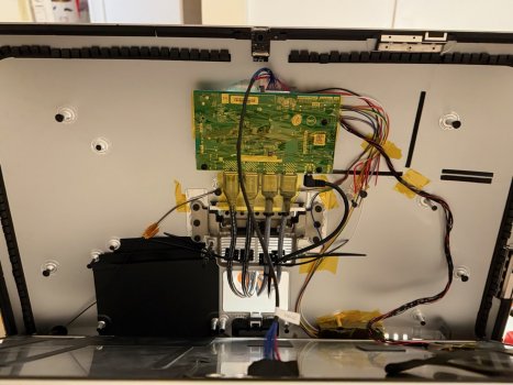
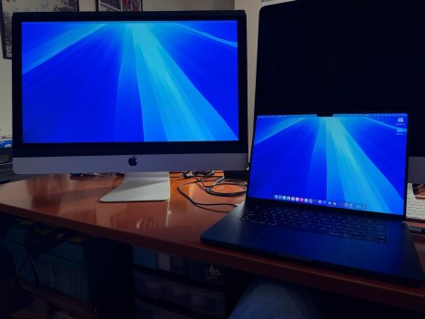
I just want to show you my setup, maybe it will help someone.
<...>
Parts list:
View attachment 2470975
- JoyIn 5-Way Switch as monitor control (DEBO SWITCH 5WS, Reichelt Germany)
View attachment 2470977
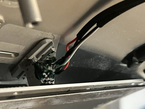
Here you see the 5 way rocker for display settings. Currently it is just held by foam parts. Right is menu, left is exit / source. Clicks very satisfying!
On / Off could also be realized with middle click but i wanted to preserve the original on / off switch.
Cheers
@mmyk I've listed the JRY Control Strip connections.
On the SA1 pin 1 is left, nearest the backlight socket.
On the FA1 the top is pin 1.
These boards are designed to be used in monitors, and the manufacturers of these monitors design their own firmware to suit the button layout of the OSDs they use.
There are more options available to these firmwares, and the extra pins on the JRY boards allow these options, like IR remote controllers etc.
Last edited:
im in the process of putting together a JYR-SA1 build and im interested in the IR remote function. I didn't know this is a thing for the JRY boards.@mmyk I've listed the JRY Control Strip connections.
On the SA1 pin 1 is left, nearest the backlight socket.
On the FA1 the top is pin 1.
These boards are designed to be used in monitors, and the manufacturers of these monitors design their own firmware to suit the button layout of the OSDs they use.
There are more options available to these firmwares, and the extra pins on the JRY boards allow these options, like IR remote controllers etc.
what do I need to get that feature. an IR remote would be amazing to control the monitor.
any link to the product would also be helpful so I know what to buy. thanks!
@Bassy_92
There is no sign that there is IR functionality on any of the JRY boards that can be enabled.
Even the Chinese 4K monitor that uses the SA1 board doesn't have an IR remote.
Whether it's just a firmware problem, or if the IR circuitry isn't actually built into the board, is unclear.
Only the R1811/R9A18 have a usable remote control.
@eschneider5
"I'd like to do the 5K conversion . I purchased a 2017 iMac and was hoping you could guide me as to best setup. I'd like to get the full 10bit color and I purchased this display because it is supposed to have the best color profile options. what do I need to make sure everything is optimized?
I will be connecting my 2017 MBP which says it supports up to 2 5K displays...."
Read this post I made.
There is an important point to bear in mind: Only Macs introduced after 2019 can drive a 5K monitor with one cable.
A 2017 Mac can only drive a monitor at 4K resolution with one cable.
But there is a board, the R9A18 which works at 5K but needs to be driven by two cables (USB-C to DisplayPort), so it has to use two TB3 ports on your MBP.
The R9A18 works like this so would be the best to use.
But, if you plan to get a newer Mac anytime soon then you could use a R1811 board, which supports single DP 1.4 cable 5K with newer Macs.
BUT TO USE YOUR 2017 MBP WITH THE R1811 you have to have special firmware flashed onto the R1811, (called DP 1.2 QQ1), and the flashing process has to be done with a Windows computer that has a DP port.
The board seller who is expert in this process is StoneTaskin.com, who sell the R1811 board and the DP 1.2 firmware, and probably can do the flashing as well.
All the specific build details depend on your skill level at constructing this sort of thing.")
And whether you have experience of building electronic projects....
It's best to ask any more questions here on the end of the DIY Monitor Success thread once you have decided the sort of thing you want to do.
"I'd like to do the 5K conversion . I purchased a 2017 iMac and was hoping you could guide me as to best setup. I'd like to get the full 10bit color and I purchased this display because it is supposed to have the best color profile options. what do I need to make sure everything is optimized?
I will be connecting my 2017 MBP which says it supports up to 2 5K displays...."
Read this post I made.
There is an important point to bear in mind: Only Macs introduced after 2019 can drive a 5K monitor with one cable.
A 2017 Mac can only drive a monitor at 4K resolution with one cable.
But there is a board, the R9A18 which works at 5K but needs to be driven by two cables (USB-C to DisplayPort), so it has to use two TB3 ports on your MBP.
The R9A18 works like this so would be the best to use.
But, if you plan to get a newer Mac anytime soon then you could use a R1811 board, which supports single DP 1.4 cable 5K with newer Macs.
BUT TO USE YOUR 2017 MBP WITH THE R1811 you have to have special firmware flashed onto the R1811, (called DP 1.2 QQ1), and the flashing process has to be done with a Windows computer that has a DP port.
The board seller who is expert in this process is StoneTaskin.com, who sell the R1811 board and the DP 1.2 firmware, and probably can do the flashing as well.
All the specific build details depend on your skill level at constructing this sort of thing.
And whether you have experience of building electronic projects....
It's best to ask any more questions here on the end of the DIY Monitor Success thread once you have decided the sort of thing you want to do.
Last edited:
Amazing! Thank you for the thorough response. I think I'll go for the R1811 board and buy a Mac mini as they are very well priced and deal with the lower res for the '17 MBP. One more question for everyone, is reusing the stock speaker with the crossovers worthwhile? It seems most have experienced less than stock performance with the aftermarket conversion from what I've seen. The crossovers are relatively inexpensive so i would like to do it unless everyone says it's not worthwhile.
I built mine with this setup. And very pleased with the stock speakers. Very easy build. But I was only trying to get good sound, instead of no speakers at allOne more question for everyone, is reusing the stock speaker with the crossovers worthwhile?
@eschneider5 "I think I'll go for the R1811 board and buy a Mac mini..."
With a new M4 Mac mini the HDMI 2.1 port is able to do 5K, so getting the R1811 board with the HDMI 2.1 upgrade is worth while if you think you might run out of the (3) USB-C TB4 ports...
"...is reusing the stock speaker with the crossovers worthwhile?"
Using the iMac speakers can give a good enough result, not as good as an external HiFi setup, but fine for general use.
One further point about the R9A18: it can be used to give 5K with earlier Macs using only one cable, using a Thunderbolt 3 to dual DP 1.2 adapter. Then two DP cables to the R9A18.
This setup works fine with recent Macs as well.
Also the R9A18 has the same audio amp as the R1811, so can be used for the speakers.
@Kaeslin has done this in his conversion.
One more thing....
I read elsewhere that with the P3 displays need a backlight "booster" for the additional draw, but I don't know if that is a requirement. Please advise.
I read elsewhere that with the P3 displays need a backlight "booster" for the additional draw, but I don't know if that is a requirement. Please advise.
The R1811 on its own does about 450 nits. With the DZ-0818 constant current board this increases to about 550 nits.
For normal use 450 is absolutely fine because you are not going to be doing colour accurate work with direct light shining on the screen.
In fact selecting the P3 colour mode reduces the maximum brightness of the screen slightly, presumably to maintain accuracy, so I don’t think it’s necessary to use the CC Backlight board.
@mmyk There are two power lines on these boards - unswitched, which is on whenever the board's PSU is providing power, and switched, which will turn off when the board goes into standby.
There is a possible place where you might get access to a power line. (You would have to test):
There is a 12 pin connector to connect a Constant Current backlight driver board, with at the lower end pins 1-4 DCIN (+) and 5-7 GND (–) pins, which could well supply switched 12v?
Or maybe unswitched...
On the R1811, there is a duplicate socket (where V3 boards took 12v for the heatsink fan) which can supply a switched source.
@mmyk If you are unable to locate a terminal to use for 12 Vdc on your LCD driver board, you have another option - use a step down voltage converter such as this. These are small boards that should easily fit inside the iMac case. Just need to use another terminal on your 24Vdc power supply or splice the 24Vdc power line connecting to your LCD driver board and feed it to the input terminals of the converter and then run wires from the output terminals to your 12Vdc load.Would anyone know if JRY--SA1/FA1 boards have any sort of 12VDC output to feed some other pieces of electronics?
Last edited:
As an Amazon Associate, MacRumors earns a commission from qualifying purchases made through links in this post.
Hi all, thanks for the suggestions. I was looking if there was a switched 5 or 12VDC output to control some other relay in my build which I am still planning to do. Now I am considering to hook up onto pins for the green LED on the daughter board. Otherwise I'll probably go with step-down converter. Still, these other components would require 12V power supply.@mmyk If you are unable to locate a terminal to use for 12 Vdc on your LCD driver board, you have another option - use a step down voltage converter such as this. These are small boards that should easily fit inside the iMac case. Just need to use another terminal on your 24Vdc power supply or splice the 24Vdc power line connecting to your LCD driver board and feed it to the input terminals of the converter and then run wires from the output terminals to your 12Vdc load.
Once I get my hands on the board I'll see if it works on 12V power supply as I'd like to reuse the original PSU. That would also simplify the things by avoiding of dealing with both 24 and 12V at the same time.
As an Amazon Associate, MacRumors earns a commission from qualifying purchases made through links in this post.
You got quite the bargain on that 2015 iMac!Time to share an update the final form of my simple FA1 5K conversion!
I popped out the logo from the back, mounted the board FA1 at the top of the case, and the heat sink pumps hot air right out the opening. Working on a 3d printed insert with slats which will slip in the opening.
The board is mounted on nylon standoffs which were affixed to the case. Roughed the smooth case, cleaned with IPA, hot glued down.
DP & HDMI female extensions run out the RAM slot. Zip tied the cables to the case via 3M adhesives for tension relief.
A 5 position joystick to control the board has access out the Ethernet port. It's sandwiched between the case and some foam.
I avoided new adhesive on the screen by using black painters tape instead. It's easy to remove and get back in if I need and much more pleasing than the blue tape!
Parts list comes in under $500:
• 5K Late 2015 • $150 FB Marketplace
• JRY-W9RQUHD-FA1 • $168 Stone Taskin
• HDMI 8K Extension (2) • $26 Amazon
• DP 8K Extension (2) • $10 Amazon
• USB-C to DP Cable (2) • $23 Amazon
• SHNITPWR 24V 8A External Power Supply • $30 Amazon
• 5 Direction Navigation Module (5-pack) • $9 Amazon
• 3.5mm Audio Extension • $6 Amazon
• 2" Kapton Tape • $13 Amazon
• 1" x 20 yards black painters tape • $7 Amazon
• M3 Nylon Hex Spacers • $10 Amazon
As an Amazon Associate, MacRumors earns a commission from qualifying purchases made through links in this post.
Register on MacRumors! This sidebar will go away, and you'll see fewer ads.