Become a MacRumors Supporter for $50/year with no ads, ability to filter front page stories, and private forums.

cmdrdata

macrumors 6502
Jun 10, 2011
377
2
Dallas, Texas, USA
I just received the cap 47pf, replaced it but I'm still getting 1.9V. Now I'm wating for 2k Ohm resitor, I will tack it on the top of the other one to see any voltage changes. Let's say if that won't be enough to get the SDA line going do you suggest maybe a quick reflow of the charger IC or SMC chip. Or you think that wont help?

I bet you one hundred monopoly dollar that reflow will not solve your problem.
If you have a good SMD work station with high magnification microscope, you can try lifting the leg of the SMC identified as the SDA signal line (and if that doesn't do it, the leg of CHARGER IC). This should allow the SDA line to float to G3HOT voltage. HOWEVER, these legs are quite brittle, it can only be bent 1 -2 times and then you are toast.
 

U-234

Suspended
May 16, 2012
72
0
Chicago, IL
I bet you one hundred monopoly dollar that reflow will not solve your problem.
If you have a good SMD work station with high magnification microscope, you can try lifting the leg of the SMC identified as the SDA signal line (and if that doesn't do it, the leg of CHARGER IC). This should allow the SDA line to float to G3HOT voltage. HOWEVER, these legs are quite brittle, it can only be bent 1 -2 times and then you are toast.

I do have good scope and i see how small that leg is even with that magnification, it would be very risky to lift it. I did some more measurements and on Q7055 pin4 I'm getting 4.2V where on the fully working logic board I'm getting 4.3324V this is CHGR BGATE line. Not a significant difference but because it is part of the battery charging load it might have some connection to our 1.9V. Is there another way to 'neutralize' that leg without lifting it? I don't know if there are any methods of doing that espacially for troubleshooting purposes. I liked your idea of tacking on another resitor for example I think it is a good workaround/test without removing the component to see any voltage changes.
 

cmdrdata

macrumors 6502
Jun 10, 2011
377
2
Dallas, Texas, USA
I do have good scope and i see how small that leg is even with that magnification, it would be very risky to lift it. I did some more measurements and on Q7055 pin4 I'm getting 4.2V where on the fully working logic board I'm getting 4.3324V this is CHGR BGATE line. Not a significant difference but because it is part of the battery charging load it might have some connection to our 1.9V. Is there another way to 'neutralize' that leg without lifting it? I don't know if there are any methods of doing that espacially for troubleshooting purposes. I liked your idea of tacking on another resitor for example I think it is a good workaround/test without removing the component to see any voltage changes.

In my early days of digital design and circuit building, I used to clip the legs of an IC and then lift of each soldered legs one at a time, but that was then. The chip nowadays is so tiny it needs an SMD workstation to remove it. In your case, if you can somehow cut that leg but not bend or move it, you may be able to test it. If nothing changed then you can bridge it with a swipe of solder.
CHGR_BGATE has nothing to do with 1.9v you are seeing. That is the CHARGER IC output that drives the FET so charging current or battery power can flow either way. That IC by the way is powered by one of the 5v regulator derived from PPBUS_G3H (12v).
 

Mori3000

macrumors member
Mar 13, 2012
49
0
Problem with Macbook pro 15 1286 2010

Hello

I have got a MBP which has spilled water on it and it could not start.

I have cleaned up the board with Alcohol 99%, and then the MBP started working and the keyboard had problem too which i replaced it.

But there is still one more problem, when i connect the Megasafe the MBP turns on directly and the light on the megasafe is only green and it is not charging the computer.

If i disconnect the battery, the MBP can not start only by Megasafe and i must have a charged battery to make it work.

By other word it is working only by battery and i can not charge it.

I found a short on the board close to SMC chip which i send the photo now.

I do not know if what i did is right or not:(
 

Attachments

  • IMG_0118[1].JPG
    IMG_0118[1].JPG
    1.1 MB · Views: 735
  • IMG_0107[1].JPG
    IMG_0107[1].JPG
    2.2 MB · Views: 539
  • IMG_0110[1].JPG
    IMG_0110[1].JPG
    2.3 MB · Views: 604
  • IMG_0108[2].JPG
    IMG_0108[2].JPG
    1.7 MB · Views: 696

cmdrdata

macrumors 6502
Jun 10, 2011
377
2
Dallas, Texas, USA
Hello

I have got a MBP which has spilled water on it and it could not start.

But there is still one more problem, when i connect the Megasafe the MBP turns on directly and the light on the megasafe is only green and it is not charging the computer.

If i disconnect the battery, the MBP can not start only by Megasafe and i must have a charged battery to make it work.

By other word it is working only by battery and i can not charge it.

I found a short on the board close to SMC chip which i send the photo now.

I do not know if what i did is right or not:(

1. Do you have green LED with magsafe only? If yes, then the DCIN fuse is OK. If not, check that fuse (located close to the DCIN plug (on the hidden side of the board).
2. Since the system will boot on battery power, the circuit beyond the system fuse (near the battery plug) is OK. That leaves the charging circuitry consisting of several power FETs and resistor, capacitor and inductors. Also since it will not boot on magsafe only, you have to check that G3HOT (3.4v) is present when magsafe is connected (see the two test pin that starts the system on the logic board. One of that pin should be 3.4v and the other at 0v. If they both are at 3.4v, then there is a short, thus causing the system to start up immediately (when battery is on and magsafe then plugged in).
 

U-234

Suspended
May 16, 2012
72
0
Chicago, IL
In my early days of digital design and circuit building, I used to clip the legs of an IC and then lift of each soldered legs one at a time, but that was then. The chip nowadays is so tiny it needs an SMD workstation to remove it. In your case, if you can somehow cut that leg but not bend or move it, you may be able to test it. If nothing changed then you can bridge it with a swipe of solder.
CHGR_BGATE has nothing to do with 1.9v you are seeing. That is the CHARGER IC output that drives the FET so charging current or battery power can flow either way. That IC by the way is powered by one of the 5v regulator derived from PPBUS_G3H (12v).


Do you know if that battery charger chip makes any difference?

On the schematic it shows as ISL6259 but on the chip itself it is printed ISL6259A you think "ISL6258A" should be ok? Is it the same as ISL6259?

Now ISL6259 or ISL6259A is nowhere to be found, digikey has it as ISL6258A...i'm little bit confused. :(

http://www.digikey.com/scripts/dksearch/dksus.dll?vendor=0&keywords=ISL6258AHRTZ
 

cmdrdata

macrumors 6502
Jun 10, 2011
377
2
Dallas, Texas, USA
Do you know if that battery charger chip makes any difference?

On the schematic it shows as ISL6259 but on the chip itself it is printed ISL6259A you think "ISL6258A" should be ok? Is it the same as ISL6259?

Now ISL6259 or ISL6259A is nowhere to be found, digikey has it as ISL6258A...i'm little bit confused. :(

http://www.digikey.com/scripts/dksearch/dksus.dll?vendor=0&keywords=ISL6258AHRTZ
6259 and 6259A are probably interchangeable, but I'd think that 6258 is slightly different perhaps in voltage/current to threshold limits. Searching eBay turned out a few 6259 chips.
 

U-234

Suspended
May 16, 2012
72
0
Chicago, IL
6259 and 6259A are probably interchangeable, but I'd think that 6258 is slightly different perhaps in voltage/current to threshold limits. Searching eBay turned out a few 6259 chips.

Yes, I saw it they have few listed the only difference is mine has 'exposed pads' where the one on eBay doesn't. With exposed pads that's how i'm able to measure all the pins. Not sure if originaly having exposed pins chip it is ok to change it to the one without the pins exposed.

Let me give you little update on the 1.9V - I temp connected 1k Ohm resistor on the top of the other 2KOhm resistor, my voltage on the SDA line 6 pin went up to 2.8V also on the battery charger pin10. So does this tell us anything which component might be bad except that we incread the voltage? Now, when I'm thinking about it, you think maybe I should remove the 2k Ohm and install 1k Ohm, with our voltage close to 3V maybe I should try the megsafe and see if solid green will turn into amber?

What was the formula again, what resistor I need to bump it up to get 3.4V?
 
Last edited:

cmdrdata

macrumors 6502
Jun 10, 2011
377
2
Dallas, Texas, USA
Yes, I saw it they have few listed the only difference is mine has 'exposed pads' where the one on eBay doesn't. With exposed pads that's how i'm able to measure all the pins. Not sure if originaly having exposed pins chip it is ok to change it to the one without the pins exposed.

Let me give you little update on the 1.9V - I temp connected 1k Ohm resistor on the top of the other 2KOhm resistor, my voltage on the SDA line 6 pin went up to 2.8V also on the battery charger pin10. So does this tell us anything which component might be bad except that we incread the voltage? Now, when I'm thinking about it, you think maybe I should remove the 2k Ohm and install 1k Ohm, with our voltage close to 3V maybe I should try the megsafe and see if solid green will turn into amber?

What was the formula again, what resistor I need to bump it up to get 3.4V?

I'd try leaving the doubled up resistor in place and then connect the magsafe. If it goes orange then you will know that the charger is communicating and SMC might detect battery present. You should not lower the resistance anymore than what you have done as it will cause that open collector transistor to be overloaded when attempting to drive the SDA line to logic low. Can't tell which one, but that 6259 or the SMC is the culprit.
 

rickAC

macrumors member
May 16, 2012
36
1
I have a similar problem. It's a Macbook 1180, 820-2279.

SMC_ADAPTER_EN at U6950 is only 1,8V instead of 3,4V. That way ACIN ENABLE GATE doesn't switch Q6910 and as a result Sys Onewire is 0V.

I couldn't find the reason why there is only 1,8V, all resistors from SMC IC to U6950 are ok so I soldered pin 1 (SMC_ADAPTER_EN) and pin 2 (SMC_BC_ACOK which is 3,4V) at U6950. It now activate Q6910 and Sys_onewire is 3,4V.
But there is no light on Magsafe. It starts in bypass mode though.
 

rickAC

macrumors member
May 16, 2012
36
1
I found out. Now everything is working.
I new it was SMC IC somewhere but first after I took a good LB and measured
every test point around SMC I found out that SMC_ADAPTER_EN was too low
(1,8V) as well as NC_SMC_RSTGATE_L (2,2V should be 3,4V).

Now, luckily these two wasn't shorted so I found nearest 3,4V (PM_LAN_PWRGOOD test point) to SMC_ADAPTER_EN test point and bridged them together.
Then I bridged NC_SMC_RSTGATE_L test point to SMC_RESET_L (U5000 pin 1). After I switched the power on there was a light in Magsafe and the fan started promptly with a question mark on screen.

I will attach the measurings and I hope that way we could share more what we have.

SMC testpoints.jpg
 

rickAC

macrumors member
May 16, 2012
36
1
Hi,

I have yet another Macbook A1180 /820-2279 (K36). A visual inspection showed that LB, precisely Q7902 got a stroke and shorted everything (some IC got really warm). The only way was to take it out and see if short still was there. Luckily it wasn't. I haven't soldered another one yet. See attachment.

Do you know if that is why I only got 4v at Q7901 (CHGR_PHASE)? In other words how these 12,5V get there? Is it U7900 (Charger IC) that increase the voltage from CHGR_BOOT (via D7900 diode) or is it Mosfets in pair that regulate the 12v voltage?

Thanks


Untitled.jpg
 

cmdrdata

macrumors 6502
Jun 10, 2011
377
2
Dallas, Texas, USA
Hi,

I have yet another Macbook A1180 /820-2279 (K36). A visual inspection showed that LB, precisely Q7902 got a stroke and shorted everything (some IC got really warm). The only way was to take it out and see if short still was there. Luckily it wasn't. I haven't soldered another one yet. See attachment.

Do you know if that is why I only got 4v at Q7901 (CHGR_PHASE)? In other words how these 12,5V get there? Is it U7900 (Charger IC) that increase the voltage from CHGR_BOOT (via D7900 diode) or is it Mosfets in pair that regulate the 12v voltage?

Thanks


View attachment 348639

Q7901 and Q7902 operates in push-pull method to create square waves, with the duty cycle constantly adjusted by the charger IC so that when it is filtered by the capacitor/resistor/choke on the output of it becomes 12v nominal (this is the classic concept of switching regulator). Since Q7902 is shorted, the charger IC turns Q7901 harder to bring the output to 12v, but unable to do so as high currents are flowing to ground each time Q7901 is turned on.

PS: can you send me the brd file, I can't seemed to find it in p21 that you mentioned.
 

rickAC

macrumors member
May 16, 2012
36
1
Thanks.
The thing is there is no option to attach a file to PM.
But here is a link to it. You have to be logged on, you know it.
 

U-234

Suspended
May 16, 2012
72
0
Chicago, IL
I'd try leaving the doubled up resistor in place and then connect the magsafe. If it goes orange then you will know that the charger is communicating and SMC might detect battery present. You should not lower the resistance anymore than what you have done as it will cause that open collector transistor to be overloaded when attempting to drive the SDA line to logic low. Can't tell which one, but that 6259 or the SMC is the culprit.

I temp connected 1K Ohm 1/4W resistor (the regular through whole) I avoided soldering, the Voltage on the Battery Connector (pin6) went up to 2.8V. While holding the resitor and measuring that I still have 2.8V I connected megsafe. Unfortunately the light didn't turn amber. So you think 2.8V wasn't enough versus what I'm supposed to have 3.4 or this is clear idication that either SMC is bad or ISL6259. If that is the case is there another test I can do to determine which one is bad or at least try to eliminate?

I guess I can always start with the 'easier' one and replace ISL6259, if that would turn light to amber we have a winner if not - than I think SMC would be the culprit. Please advise.

Update: I removed ISL6259A, now I'm getting 150K Ohms on the SDA line as supposed to 6k Ohms before. On working LB with battery charger installed I'm getting 26K Ohms.
 
Last edited:

mac-n-sauce

macrumors regular
Jun 25, 2012
209
2
Tampa, Fl
Do you know if that battery charger chip makes any difference?

On the schematic it shows as ISL6259 but on the chip itself it is printed ISL6259A you think "ISL6258A" should be ok? Is it the same as ISL6259?

Now ISL6259 or ISL6259A is nowhere to be found, digikey has it as ISL6258A...i'm little bit confused. :(

http://www.digikey.com/scripts/dksearch/dksus.dll?vendor=0&keywords=ISL6258AHRTZ

I have a source where these are both available ISL6259, ISL6259A around $8.00 us money
 

cmdrdata

macrumors 6502
Jun 10, 2011
377
2
Dallas, Texas, USA
I temp connected 1K Ohm 1/4W resistor (the regular through whole) I avoided soldering, the Voltage on the Battery Connector (pin6) went up to 2.8V. While holding the resitor and measuring that I still have 2.8V I connected megsafe. Unfortunately the light didn't turn amber. So you think 2.8V wasn't enough versus what I'm supposed to have 3.4 or this is clear idication that either SMC is bad or ISL6259. If that is the case is there another test I can do to determine which one is bad or at least try to eliminate?

I guess I can always start with the 'easier' one and replace ISL6259, if that would turn light to amber we have a winner if not - than I think SMC would be the culprit. Please advise.

Update: I removed ISL6259A, now I'm getting 150K Ohms on the SDA line as supposed to 6k Ohms before. On working LB with battery charger installed I'm getting 26K Ohms.

Which one caused the low voltage reading? That's a tough call. In the battery I2C circuit problem you are having, the MASTER is the SMC and everyone else hanging on it is the SLAVE. Serial communication always starts with the SMC sending a READ ADDRESS and then listens for DATA from slave or WRITE ADDRESS followed by DATA (on SDA line). The 2.8v I think is good enough to be "logic 1", but if the open collector driver in SMC or ISL6259 cannot drive/pulse the SDA line because it is stress damaged, you will have no communication. On a hunch (based on resistance reading), maybe the ISL6259 is the culprit since without it the impedance went to 150K ohm without the chip installed. But it is a toss of a coin.
 

DjErase

macrumors newbie
Jun 22, 2012
13
0
Resistor ?

Hi everyone,

I'm back from holiday and I re-read all the 27 pages from this thread.
Just to resume I have the green light on magsafe but no battery is detected and the battery is not charged. Battery is right, Macbook A1278.
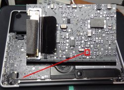
Is someone tell me the value of this resistor (see picture)? Actually there is a short-circuit but maybe it's not a resistor my eyes are old ;).

Thanks.
 

Attachments

  • MAcBookProRes.jpg
    MAcBookProRes.jpg
    1,004.2 KB · Views: 10,212

cmdrdata

macrumors 6502
Jun 10, 2011
377
2
Dallas, Texas, USA
Hi everyone,

I'm back from holiday and I re-read all the 27 pages from this thread.
Just to resume I have the green light on magsafe but no battery is detected and the battery is not charged. Battery is right, Macbook A1278.
Is someone tell me the value of this resistor (see picture)? Actually there is a short-circuit but maybe it's not a resistor my eyes are old ;).

Thanks.

Maybe you have similar problem as U-234. On the battery connector (9-pin), check the voltages with respect to ground and plug connected to logicboard. You should have
1/2/3 = 0v,
4/6=3.4v,
5 = 0v
7/8/9 = 12.5 (if fully charged)
 

Dadioh

macrumors 65816
Original poster
Feb 3, 2010
1,123
36
Canada Eh?
Hi everyone,

I'm back from holiday and I re-read all the 27 pages from this thread.
Just to resume I have the green light on magsafe but no battery is detected and the battery is not charged. Battery is right, Macbook A1278.
Is someone tell me the value of this resistor (see picture)? Actually there is a short-circuit but maybe it's not a resistor my eyes are old ;).

Thanks.

I measured 2 boards and they both measured 5 ohms for that resistor. When I touch my leads together I get 0.5 ohms so it seems a bit higher than a zero ohm resistor but within margin of error.
 

U-234

Suspended
May 16, 2012
72
0
Chicago, IL
Maybe you have similar problem as U-234. On the battery connector (9-pin), check the voltages with respect to ground and plug connected to logicboard. You should have
1/2/3 = 0v,
4/6=3.4v,
5 = 0v
7/8/9 = 12.5 (if fully charged)

Another update on my battery issue: It appears I'm making some progress, why I did is removed ISL6259 cleaned it removed old solder, cleared the pads on the board where ISL sits and re-solder. Well, the differences are:

-now i'm getting 3.4V on SDA line
-now my laptop start of the battery even when I shut down. Before when megsafe was connected and the laptop was on, as soon as I disconnected the laptop was shuting down.

-the only thing remaining is that the led still doesn't turn amber just solid green. Now, if I look very close at that solid green I see that the solid green is very slightly pulsing (you have to look very very closely)

I tried reset SMC and PRAM hoping SMC will 'change his mind' and tell ISL to charge the battery.

The battery icon has "X" which shows no batteries available. Also, in system profiler is shows no battery installed. So at least now I can use the laptop in portable mode without megsage connected. Where before only in 'desktop' mode with megsage connected.

So, you think that ISL is bad and is telling the OS 'I don't see any battery'
 
Last edited:

cmdrdata

macrumors 6502
Jun 10, 2011
377
2
Dallas, Texas, USA
Another update on my battery issue: It appears I'm making some progress, why I did is removed ISL6259 cleaned it removed old solder, cleared the pads on the board where ISL sits and re-solder. Well, the differences are:

-now i'm getting 3.4V on SDA line
(snipped)
The battery icon has "X" which shows no batteries available. Also, in system profiler is shows no battery installed. So at least now I can use the laptop in portable mode without megsage connected. Where before only in 'desktop' mode with megsage connected.
So, you think that ISL is bad and is telling the OS 'I don't see any battery'

Do you have a known god battery? If yes, try that.
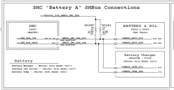
As I understand it, SMC is the MASTER, so it sends a read status to the battery asking for a response and battery status. If it gets "I am near death code", the SMC reports a "Replace Battery Soon" message that gets displayed on your desktop battery icon. If the SMC doesn't get any response from the battery or battery is in shutdown or self protective mode, it displays an "X" on the battery icon. The ISL625x is also a SLAVE to SMC, so it receives charging directives from the SMC based upon battery charge status that the SMC gets from the battery itself. See the attached block diagram for A1278 (logic board version M97A, early 2009).
 

Attachments

  • Screen Shot 2012-07-21 at 7.13.49 PM.png
    Screen Shot 2012-07-21 at 7.13.49 PM.png
    45.1 KB · Views: 558
Register on MacRumors! This sidebar will go away, and you'll see fewer ads.