Become a MacRumors Supporter for $50/year with no ads, ability to filter front page stories, and private forums.

cmdrdata

macrumors 6502
Jun 10, 2011
377
2
Dallas, Texas, USA
Thanks mac.

What do and other think the problem is? Could it be U7000? In some of mb and mbplogic boards I had it was mostly Phase and UGate that was shorted to ground but this one is ok. No short around IC.

Q7000 gate signal being 16v is BAD. That gate should have approx 16.5v x (R7001/(R7001+R7098)) = 6.3v IF U7000 is enabling Q7000 by pulling pin1 to "ground". If that gate signal is correct, it will turn Q7000 on allowing the voltage to go to the next FET. So my guess is that U7000 pin internal open collector transistor maybe bad (assuming also that R7001 and R7098 have the correct values). If that pin is not bad, then the SMC thinks that it is not getting the correct status from the adapter (SCL/SDA communication), thus it sends an "isolate adapter" signal resulting in pin 1 to float close to magsafe voltage (16v) and thus preventing magsafe power to reach the next FET Q7001.
 
Last edited:

mac-n-sauce

macrumors regular
Jun 25, 2012
209
2
Tampa, Fl
Q7000 gate signal being 16v is BAD. That gate should have approx 16.5v x (R7001/(R7001+R7098)) = 6.3v IF U7000 is enabling Q7000 by pulling pin1 to "ground". If that gate signal is correct, it will turn Q7000 on allowing the voltage to go to the next FET. So my guess is that U7000 pin internal open collector transistor is bad (assuming also that R7001 and R7098 have the correct values.

Ok, so in english for us simple folk, well at least for me, Are you saying that the IC chip is defective causing the low voltage on the Q7000 not letting it turn on and pass through to Q7001?

If that is the case, does the U7000 get a voltage reading from the dcin direct and then send it to the Q7000 or does it go through the Q7000 first then to the U7000. If it is the latter, then doesn't that make the Q7000 bad based on Rick's values?
Where did you learn all this stuff by the way?
 

rickAC

macrumors member
May 16, 2012
36
1
Ok, so in english for us simple folk, well at least for me, Are you saying that the IC chip is defective causing the low voltage on the Q7000 not letting it turn on and pass through to Q7001?

If that is the case, does the U7000 get a voltage reading from the dcin direct and then send it to the Q7000 or does it go through the Q7000 first then to the U7000. If it is the latter, then doesn't that make the Q7000 bad based on Rick's values?
Where did you learn all this stuff by the way?

Hi,
How about your readings on pin 1? Is it a working board or cdmrdata is mistaken here (it happens rare to him :))?
What I found out, on basis of your readings, is that SMBUS_CHGR_SDA measures 5 ohm and SMBUS_CHGR_SCL aprox. 10 ohm. Is this short enough for U7000 not to output the right voltages on PPBUS?

P.S.
Mac, have you got my PM?
 

cmdrdata

macrumors 6502
Jun 10, 2011
377
2
Dallas, Texas, USA
Ok, so in english for us simple folk, well at least for me, Are you saying that the IC chip is defective causing the low voltage on the Q7000 not letting it turn on and pass through to Q7001?

If that is the case, does the U7000 get a voltage reading from the dcin direct and then send it to the Q7000 or does it go through the Q7000 first then to the U7000. If it is the latter, then doesn't that make the Q7000 bad based on Rick's values?
Where did you learn all this stuff by the way?

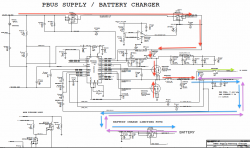
Attached is the PBUS page of the K24 schematic showing how the typical MAC SYSTEM power data flows, meaning these are the high current (amperes, not micro or milliamps) paths.

1. RED is power flow from magsafe
2. VIOLET is power flow from battery
3. BLUE is charging current from magsafe to battery
4. GREEN is power to the system (12v nominal PPBUS_G3H) from either battery or magsafe

Any other components connected to these lines are usually sense or signal lines and typically are voltage divided by two resistors (one end to GND) so the FET or IC CHIP like U7000 can sense the tap point of two resistors in series what voltage it is seeing.

On your question, I am not saying U7000 is absolutely bad. It could be, but the fact that Q7000 gate read 16v in one of the previous posted image (meaning pin1 of U7000 is not pulling that line to 0v to allow the voltage divider to work as it should is a problem. Unfortunately U7000/CHARGER IC is not a simple thing. There could be other reasons why that line is not being pulled low/0v by the IC, i.e., SMBUS communication. I will post how I think the CHARGER work later.

PS: I used to design digital circuits for F4 jet avionics, so I know a LITTLE on how to read and follow schematics. :)
 

Attachments

  • Screen Shot 2012-09-30 at 8.02.00 AM.png
    Screen Shot 2012-09-30 at 8.02.00 AM.png
    178.4 KB · Views: 807

U-234

Suspended
May 16, 2012
72
0
Chicago, IL
I agree based on my AHT error PBus rail voltage below limit I was looking at all the pages with PBus. Two of them I already attached. On the Power Block Diagram I checked the voltage like you sugested. R5400 - 12V, ISL95870 - 1.05V and R7640 - 1.05V. So it appears the voltage is fine here.

I did the test on other working LB and the AHT revealed 12V on the VPOR sensor where on my other LB with the VPOR sensor issue it measured 0.5V. So where is the VPOR sensor getting that value from? Only 0.5V where I should be getting 12V.

Other PBus section is on page 49 (Voltage & Load side current sensing) 7D which refers to Q5300 - to me that sounded more like a sensor. It had few burned legs so I replaced it with a new one. However, that appeared not to make any effect on my 0.5V below limit voltage.

cmdrdata - so what you suggest to check next for tracing that VPOR sensor voltage?
 

Attachments

  • Capture.PNG
    Capture.PNG
    102.5 KB · Views: 307

cmdrdata

macrumors 6502
Jun 10, 2011
377
2
Dallas, Texas, USA
cmdrdata - so what you suggest to check next for tracing that VPOR sensor voltage?

I don't have a complete schematic of this MBP (K90I), so it is hard for me to determine if your 1v output is wrong or not (email me privately for the schematic if you want me to look at it). The 3-page schematic you posted earlier is not enough data for me to determine that. In almost all Macs, the 12v PPBUS_G3H is routed through several regulators to generate different sub-voltages that the system needs, i.e., 5v, 3.3v, 1.8v, 1.05v, 1.082v, etc. Even more confusing is that some of the same voltages are generated by two or more regulators as defined by the S# and I think the S means "stage or state". Thus S0 voltage is generated before S5. For example in MBP13 K24 schematic p65, there are two low power regulators, both getting input from 3.3v and both generating 1.05v, but the PLL supply is generated at time S0, whereas AUXC 1.05v is generated at S5 (the EN pin controls when the supply comes up.
 

rickAC

macrumors member
May 16, 2012
36
1
Besides SMBUS_CHGR_SDA (5 ohm) and SMBUS_CHGR_SCL (17 ohm) I found out that PP3V42_G3H_REG has very low resistance: 54 ohm. I don't understand how the voltage of 3,42V is there in spite of low resistance. All other pins are ok.
 

cmdrdata

macrumors 6502
Jun 10, 2011
377
2
Dallas, Texas, USA
Besides SMBUS_CHGR_SDA (5 ohm) and SMBUS_CHGR_SCL (17 ohm) I found out that PP3V42_G3H_REG has very low resistance: 54 ohm. I don't understand how the voltage of 3,42V is there in spite of low resistance. All other pins are ok.

These SMBUS lines are pulled up to 3.42v by typically a 2k or 1k Ohm resistors (depending on which MBP model it is). So if you measure with power disconnected) between G3HOT source and the SDS or SCL line you should see something near or below those values. How did you measure those resistance?
If you got those values by measuring with respect to ground, it doesn't make sense because then the voltage reading would be very low because:

G3HOT -> 2k resistor -> SCLorSDA -> device(s) connected/impedance -> GND, and in your case you are saying device(s) impedance is 5 or 17 ohms. Device impedance when not attempting to pulse the line is usually quite high, more than 100K, thus if you measure the voltage at that point it will be close to 3.42 since the pull up resistor will be negligible wrt to the device impedance.
 

rickAC

macrumors member
May 16, 2012
36
1
These SMBUS lines are pulled up to 3.42v by typically a 2k or 1k Ohm resistors (depending on which MBP model it is). So if you measure with power disconnected) between G3HOT source and the SDS or SCL line you should see something near or below those values. How did you measure those resistance?
If you got those values by measuring with respect to ground, it doesn't make sense because then the voltage reading would be very low because:

G3HOT -> 2k resistor -> SCLorSDA -> device(s) connected/impedance -> GND, and in your case you are saying device(s) impedance is 5 or 17 ohms. Device impedance when not attempting to pulse the line is usually quite high, more than 100K, thus if you measure the voltage at that point it will be close to 3.42 since the pull up resistor will be negligible wrt to the device impedance.

My mbp is A1278 - k24.
I just took some measurements and for example resistance between pin 1 (PP3V42_G3H_SMBUS_SMC_BSA) on R5280 and pin 2 (SMBUS_SMC_BSA_SDA) is 54ohm.
 

cmdrdata

macrumors 6502
Jun 10, 2011
377
2
Dallas, Texas, USA
My mbp is A1278 - k24.
I just took some measurements and for example resistance between pin 1 (PP3V42_G3H_SMBUS_SMC_BSA) on R5280 and pin 2 (SMBUS_SMC_BSA_SDA) is 54ohm.

That 54 Ohm is awfully low. I'd try to unsolder that and measure it offline. It should be close to whatever the schematic indicated. If it is indeed that low, the device trying to pulse the line will be unable to pull it down low enough to be a logic zero, essentially almost 0v thus the SMC will not be able to get any status code from the charger or battery.
 
Last edited:

rickAC

macrumors member
May 16, 2012
36
1
That 54 Ohm is awfully low. I'd try to unsolder that and measure it offline. It should be close to whatever the schematic indicated. If it is indeed that low, the device trying to pulse the line will be unable to pull it down low enough to be a logic zero, essentially almost 0v thus the SMC will not be able to get any status code from the charger or battery.

Thanks for replay.

I have taken temporarily some components out but nevertheless all the same. I guess now that the faulty component is ISL6258A because both G3H and SDA&SCL (6ohm and 17ohm) are bad. If it was only G3H why it still reads
6ohm on SDA line after R5280 is taken out?
 

cmdrdata

macrumors 6502
Jun 10, 2011
377
2
Dallas, Texas, USA
Thanks for replay.

I have taken temporarily some components out but nevertheless all the same. I guess now that the faulty component is ISL6258A because both G3H and SDA&SCL (6ohm and 17ohm) are bad. If it was only G3H why it still reads
6ohm on SDA line after R5280 is taken out?

I don't know the answer to your question. On the off chance that you're reading a forward conductance on some hidden pn junction (i.e., diode like), can you reverse your probe and re-measure? Does it it still read 6 and 17 ohms?
 

rickAC

macrumors member
May 16, 2012
36
1
I don't know the answer to your question. On the off chance that you're reading a forward conductance on some hidden pn junction (i.e., diode like), can you reverse your probe and re-measure? Does it it still read 6 and 17 ohms?

Today I took out ISL6285A out with hot air station. Without ISL6285A the green light on magsafe came on and 3,3V to SDA&SCL. Resistance on G3H and SDA&SCL is about 50kohm. Pads 1&2 reads 16,7V. Resistance is also ok apart from CHGR_ACOK which is virtually 0ohm. Then I cleaned the solder from LB and an ISL6285A from a water damaged mbp (same model).

Used solder cream with flux so that there was fine layer of solder on pins (not too much but enough to make contact with the pads on LB. Managed to align it fine and used hot air again. After a while I powered the board up and magsafe started blinking. But the IC wasn't hot at all. Then I did it all again believing that there was something wrong with alignement.

But the light was blinking again. Voltages changes all the time.
Now I think that either this IC is bad too or it is ok and something more is wrong, maybe SMC.
After all I don't give up easily but I am almost there. I will maybe order a new IC as a last try.

cmdrdata: Thanks for your help and advice.
 

cmdrdata

macrumors 6502
Jun 10, 2011
377
2
Dallas, Texas, USA
Today I took out ISL6285A out with hot air station. Without ISL6285A the green light on magsafe came on and 3,3V to SDA&SCL. Resistance on G3H and SDA&SCL is about 50kohm. Pads 1&2 reads 16,7V. Resistance is also ok apart from CHGR_ACOK which is virtually 0ohm. Then I cleaned the solder from LB and an ISL6285A from a water damaged mbp (same model).

Used solder cream with flux so that there was fine layer of solder on pins (not too much but enough to make contact with the pads on LB. Managed to align it fine and used hot air again. After a while I powered the board up and magsafe started blinking. But the IC wasn't hot at all. Then I did it all again believing that there was something wrong with alignement.

But the light was blinking again. Voltages changes all the time.
Now I think that either this IC is bad too or it is ok and something more is wrong, maybe SMC.
After all I don't give up easily but I am almost there. I will maybe order a new IC as a last try.

cmdrdata: Thanks for your help and advice.
You're welcome. I also doubt if the problem is with the SMC based on your first sentence. The fact that the magsafe LED turned green when the ISL6258 is taken out, that means that the SMC was able to communicate with the magsafe via the same SCL/SDA lines (SMBUS).
 

G35C

macrumors member
Oct 2, 2012
36
0
TEXAS
MBP Wont turn on

Hi All,

My wifes laptop (MBP 13 mid 2009 c2d 2.26Ghz) suffered a minor liquid spill. Now it won't turn on. I cleaned the motherboard with 97% isopropyl alcohol and checked the fuse by the magsafe and the other by the keyboard which all tested good. The magsafe turns green when pluged in. I assume the keyboard and/or power button is non functional so I bridged the pads and it did nothing. I tested the power from the pad and got 3.4V on the left one. What should I test next? Can the Macbook turn on with the keyboard disconnected or does it need to be connected for ground?
 

G35C

macrumors member
Oct 2, 2012
36
0
TEXAS
I am not sure what solder spots you are measuring. However, look at my attached image. You should be able to read 18.5V at the point noted. If you do not have 18.5V there then I think your magsafe board needs to be replaced (or cleaned if it is liquid damaged).

Hi Dadioh,
I just measured 17.1 volts at that point. G3Hot measures 3.4V. I swapped the MagSafe Board and adapter with same results.?????
 

Disgrace

macrumors member
Dec 1, 2010
32
0
So I've just experienced something similar with my 15" late-2010 MacBook Pro, however, this thread is full of people smarter than myself with loads of electrical jargon. Also, it seems not everyone has the same issues as myself.

Just prior to shutdown (forgetting my wifi password/resetting date to 2001 before remembering again), the MagSafe was playing up and electrical vibrations came through the unibody, suggesting non-grounded power outlet but I've used it regularly before.

No liquid spills could have caused this.

- No LED on the MagSafe connector.
- No backlight.
- Full speed fans.
- "No batteries available" on battery icon.
- iStat Menus can't read anything.
- Does not sleep on screen closure.

However, I did not experience any problem starting my MacBook Pro when it shut itself off initially, which has me confused.

I don't understand logic board architecture, so it would appear a repair is not possible. I restarted the SMC with Apple website instructions, and the laptop is behaving as it did before, which is actually fine other than said issues above. No idea if the battery is being charged or drained.

Should I simply send it to Apple for repairs?
 
Last edited:

mac-n-sauce

macrumors regular
Jun 25, 2012
209
2
Tampa, Fl
Hi Dadioh,
I just measured 17.1 volts at that point. G3Hot measures 3.4V. I swapped the MagSafe Board and adapter with same results.?????

Since you mentioned liquid damage---Your keyboard is probably shorted. So disconnect the keyboard cable and then short G3Hot pins. Your power button is attached to the keyboard so if either is shorted from liquid you will not power on. Your 17.1V is fine. they rarely measure 18.5.

Let us know what you find out.

Also, did liquid hit the LCD connector? If so, I would carefully disconnect it as well.
 

perfumeseksi

macrumors newbie
Aug 7, 2012
2
0
My macbook unibody A1278 wont charge after i replaced backlight fuse

You're welcome. I also doubt if the problem is with the SMC based on your first sentence. The fact that the magsafe LED turned green when the ISL6258 is taken out, that means that the SMC was able to communicate with the magsafe via the same SCL/SDA lines (SMBUS).


Not charging after replacing backlight fuse.

Hi guys, wonder if anybody can help. i had a backlight problem with my macbook unibody. i have managed to change the backlight fuse for fully working one, used flux to do so. after this i connected everything together and switched the mac on. it did, the screen came up as well, but i have noticed that the green lights on my adapter is now not bright but very dark and it says that my laptop is not charging battery this was charging ok before. if i leave the charger in with battery it does slowly charge, but it wont start without the battery. Anybody had this problem please and could help me? Cheers guys.
 

G35C

macrumors member
Oct 2, 2012
36
0
TEXAS
Since you mentioned liquid damage---Your keyboard is probably shorted. So disconnect the keyboard cable and then short G3Hot pins. Your power button is attached to the keyboard so if either is shorted from liquid you will not power on. Your 17.1V is fine. they rarely measure 18.5.

Let us know what you find out.

Also, did liquid hit the LCD connector? If so, I would carefully disconnect it as well.

Actually I had the keyboard disconnected when I briged the G3Hot pads. Not sure why it didnt start? So i took a known faulty keyboard and plugged in the ribbon into the laptop. I then did a SMC reset procedure and it started. I will order a new keyboard and go from there. Just curious why it didnt start by bridging the G3Hot pads. Could it be related to a ground issue?
 

G35C

macrumors member
Oct 2, 2012
36
0
TEXAS
Come to think of it... maybe what I should do is a photo of each side of the board with critical components identified for the use of those willing to deep dive into board level diagnostics. I'll add it to my "to do" list :)

YES!!! Please provide this for us. That would be great reference material.
 

G35C

macrumors member
Oct 2, 2012
36
0
TEXAS
Good news: I got my MBP late 2009 working again. Magsafe power works, battery power works, separately or together. Sadly, in the process of putting the logic board back into the unibody, the battery indicator flex cable broke off, so that piece is now on order (922-0828-A). Afterwards, I attempted to upgrade the OS to Snow Leopard, but alas, it seemed that the superdrive is also defective. It was unable to read the OS disk. I heard the disk spin, then it spits it out. So that too will need to be looked into, a task for another day.

So what did you do to resolve the issue with it not starting after replacing the DC-IN board. Just learning from these old post.
 

G35C

macrumors member
Oct 2, 2012
36
0
TEXAS
Actually I had the keyboard disconnected when I briged the G3Hot pads. Not sure why it didnt start? So i took a known faulty keyboard and plugged in the ribbon into the laptop. I then did a SMC reset procedure and it started. I will order a new keyboard and go from there. Just curious why it didnt start by bridging the G3Hot pads. Could it be related to a ground issue?

By faulty keyboard I mean some keys are not working. Basically I have an external keyobard that I can connect through the motherboard.
 

rickAC

macrumors member
May 16, 2012
36
1
I got it working at last. The IC should jest have more hot air. Finally I could read 12,5V on PPBUS. Everything works fine now (assembled) apart from charging the battery. After all I am satisfied with it. I will just use AC power. But something bothers me. C7043 (CHGR_CSOP and CHGR_CSON) fell off when I used hot air (I used alu foil and covered everything surraunding the IC) and I forgot to solder a new one. Could it be the reason why charging doesn't work? Pins 7,8 and 9 on battery connector have 11,75V without battery connected. Pins 4&6 have 3,3V. Nothing on pin 5.

About G3Hot pads for powering the board:
The image in post #6 of this thread shows the wrong location of pads. I know because I tried it when I got 12,5V on PPBUS and it didn't work. The I took a look in schematics and found that there is a resistor (two pads) on the other side of board at the right corner which is called debug button. I tried it and the fan started. There are many who wrote about not being able to power board up using the wrong pads.
The image attached shows the correct location of the pads.

Debug button - on-off.jpg

Debug button - on-off - schematics.jpg
 
Last edited:
Register on MacRumors! This sidebar will go away, and you'll see fewer ads.