Become a MacRumors Supporter for $50/year with no ads, ability to filter front page stories, and private forums.

rickAC

macrumors member
May 16, 2012
36
1
I wonder if the WLED driver is detecting too much current to drive the backlight and telling the SMC to shut down. Although I have never seen this sort of behaviour.

Thanks for replay Dadioh,

After reading your assumptions I will test voltages on U9701 (WLED driver IC).
Do you know if the board has to be powered up in order to measure voltages?

For ex. on page 7 of this thread (post #158) you wrote about the enable pin (pin 4). I guess the voltage should be present without need for powering the board with G3Hot pads. What do you think?
 

G35C

macrumors member
Oct 2, 2012
36
0
TEXAS
Help Identify G3Hot on Earl 2011 i5 2.3Ghz

DigcHMpM4ywMQFNG.large
 

debo160

macrumors newbie
Jan 24, 2012
16
0
Does anyone have any suggestions on what to do wwhen the resister has burned the pads to a point of no repair? I have a Macbook Pro that has no wi-fi because of this.

I also have a MBP 15 charging but won't boot and a MBA 11' with the same issue. Both a liquid damage.
 

cmdrdata

macrumors 6502
Jun 10, 2011
377
2
Dallas, Texas, USA
Does anyone have any suggestions on what to do wwhen the resister has burned the pads to a point of no repair? I have a Macbook Pro that has no wi-fi because of this.

I also have a MBP 15 charging but won't boot and a MBA 11' with the same issue. Both a liquid damage.

You need to get a schematic and board view file to know where the missing pad is supposed to go. Then find a convenient component pin/pad to attach one end of that signal for the jumper wire. Then attach the other end to the resistor that no longer have the pad. If that pad is the junction of two components, you may need another jumper too. In the past (20-30 years ago), I'd use a small 30 gauge solid wire as the jumper wire. In my days, it was called wire wrap wires, usually blue in color.
 

Dadioh

macrumors 65816
Original poster
Feb 3, 2010
1,123
36
Canada Eh?

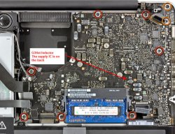
You are in luck. I just found this the other night. The inductor is noted in my attachment. The driver IC is on the back side.
 

Attachments

  • 2011_G3Hot.jpg
    2011_G3Hot.jpg
    145.1 KB · Views: 1,125

kennethf

macrumors newbie
Oct 17, 2012
17
0
Component

Hello

Anyone know the size off this component in the picture.

2010 Macbook pro 13" EMC:2351

Its waterdamaged and I try to figure out whats wrong with it.

Thanks
 

Attachments

  • A1278 component.jpg
    A1278 component.jpg
    138.3 KB · Views: 714

debo160

macrumors newbie
Jan 24, 2012
16
0
You need to get a schematic and board view file to know where the missing pad is supposed to go. Then find a convenient component pin/pad to attach one end of that signal for the jumper wire. Then attach the other end to the resistor that no longer have the pad. If that pad is the junction of two components, you may need another jumper too. In the past (20-30 years ago), I'd use a small 30 gauge solid wire as the jumper wire. In my days, it was called wire wrap wires, usually blue in color.

Ok some what like a daisy chain. I thought about that but I didn't know what the result would be. So I played it safe. There is another resistor right beside it that"s the same. I have had to replace both because they had burned out on another machine. Because both pads were destroyed by the burn out just trace them back and use wire. I will let you know the results. And Thanks!!
 

debo160

macrumors newbie
Jan 24, 2012
16
0
Ok some what like a daisy chain. I thought about that but I didn't know what the result would be. So I played it safe. There is another resistor right beside it that"s the same. I have had to replace both because they had burned out on another machine. Because both pads were destroyed by the burn out just trace them back and use wire. I will let you know the results. And Thanks!!

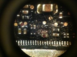
I added a pic so you could see what Im speaking of. It burned down pass the gold. After getting all the burned crap out this is whats left. The gunk is rosin/paste.
 

Attachments

  • photo.JPG
    photo.JPG
    1.9 MB · Views: 621

Dadioh

macrumors 65816
Original poster
Feb 3, 2010
1,123
36
Canada Eh?
Thanks for replay Dadioh,

After reading your assumptions I will test voltages on U9701 (WLED driver IC).
Do you know if the board has to be powered up in order to measure voltages?

For ex. on page 7 of this thread (post #158) you wrote about the enable pin (pin 4). I guess the voltage should be present without need for powering the board with G3Hot pads. What do you think?

The board needs to be booted for the WLED driver to become active. You won't see any voltages on the WLED circuit until the machine has booted to the point that it activates the backlight.
 

rickAC

macrumors member
May 16, 2012
36
1
The board needs to be booted for the WLED driver to become active. You won't see any voltages on the WLED circuit until the machine has booted to the point that it activates the backlight.


Thanks.

Before I tell how it goes with my mbp I would like to ask you the following:
Do I need to have LCD connected to LB to be able to measure voltages at for. ex. LCD connector? I ask because all those lines that comes from U1400 MCP79 (GPU) like LVDS_IG_PANEL_PWR, LVDS_IG_A_CLK_N, LVDS_IG_A_CLK_P
and all data lines are 0v when lcd is not connected and lb is booted.

This mbp is really strange. I have checked and measured every possible lead from/ to LCD connector.
At last I removed WLED driver and it makes no difference. Mbp shuts down with lcd connected. Without LCD it seems to boot ok, chime is heard).
Then it led me to other rails. PP3V3_LCDVDD_SW_F (pin 2&3 in LCD connector) 0v. It comes from U9000 > L9004.
LVDS_IG_PANEL_PWR (U9000) is 0v while vin_1 and vin_2 are 3,3v but resistance here is only 180ohm. It comes from U7200 (PP3V3_S5_REG). Is 180ohm normal or could it be the why mbp shuts down?

regards
 

macelek01

macrumors newbie
Sep 14, 2012
22
0
PPBUS_G3H voltage problem

Hello Everybody,

I would like to ask for some help from you. I've got a white macbook unibody (2010), but this doesn't power on. On the PPBUS_G3H line the voltage isn't the stable 12,6V. (It's changing 0 to 12,6V.)
The charging control ic (ISL6259) contols on a wrong way the inrush limiter FET(Q7085 - SI7149DP). The gate of this FET is controlled on a wrong way by the ISL6259 (AGATE). At this place should be stable 6V, but now it's ones 6V, than turns into about 13V. I've already replaced the ISL6259, but I still have this problem. I would be so glad if somebody could help me. To repair my mac would be very important for me.

Thank you very much for reading.
 

Attachments

  • mac_wh.png
    mac_wh.png
    702 KB · Views: 642
Last edited:

rickAC

macrumors member
May 16, 2012
36
1
Thanks.

Before I tell how it goes with my mbp I would like to ask you the following:
Do I need to have LCD connected to LB to be able to measure voltages at for. ex. LCD connector? I ask because all those lines that comes from U1400 MCP79 (GPU) like LVDS_IG_PANEL_PWR, LVDS_IG_A_CLK_N, LVDS_IG_A_CLK_P
and all data lines are 0v when lcd is not connected and lb is booted.

This mbp is really strange. I have checked and measured every possible lead from/ to LCD connector.
At last I removed WLED driver and it makes no difference. Mbp shuts down with lcd connected. Without LCD it seems to boot ok, chime is heard).
Then it led me to other rails. PP3V3_LCDVDD_SW_F (pin 2&3 in LCD connector) 0v. It comes from U9000 > L9004.
LVDS_IG_PANEL_PWR (U9000) is 0v while vin_1 and vin_2 are 3,3v but resistance here is only 180ohm. It comes from U7200 (PP3V3_S5_REG). Is 180ohm normal or could it be the why mbp shuts down?

regards


Update:

PP3V3_S5 is ok. I checked it on a good board.
I believe now that the problem is GPU.
I read nothing on these rails that comes from U4900 with mbp running:

LVDS_IG_PANEL_PWR (U9000)= 0v
LVDS_IG_A_CLK_N (L9080)= 0v
LVDS_IG_A_CLK_P (L9080)= 0v
LVDS_IG_A_CLK_F_N = 0v
LVDS_IG_A_CLK_F_P = 0v

I don't have dvi adaptor to test external video output. If it works I can use it with an external monitor or TV.
 

rickAC

macrumors member
May 16, 2012
36
1
One of the last shots Dadioh: Could it be that the sleep function is activated when LCD is connected? How can I check it?
 

longcoo817

macrumors member
Oct 23, 2011
30
0
Dallas TX
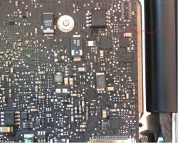
I need help identifying what this part is because it blew with slight liquid damage.
Its an early 2011 the macbook powers on right when the power is plugged but there no chime or display.
the backlight fuse is still good. smc reset turns green but then automatically powers on. This board a very slight damage on picture i could only see that one chip blown

IMG_1535.jpg


Heres a better location of it. where my arrow is pointing
2011_G3Hot.jpg
 
Last edited:

cmdrdata

macrumors 6502
Jun 10, 2011
377
2
Dallas, Texas, USA
Thanks for the pic. Now do we make jump across the pins or just 1 pin to ground to start the board?

[url=http://imageshack.us/a/img233/3291/2011g3hot.jpg]Image[/URL]

No No No. The G3HOT starting test point discussed in this forum is not shorting the actual G3HOT power supply!!!!!!!

There is a couple of pads in the logicboard where one of the pad is at 3.42v (the same as the G3HOT voltage), but THIS IS NOT the G3HOT positive power supply point. It is just a startup signal that is pulled up by a resistor to G3HOT voltage that is connected to the SMC, and when this signal is grounded by shorting the 2 test pads, it tells the SMC to start the power up sequence. DO NOT short the actual G3HOT to ground!!!!! The choke mentioned by dadioh is the power supply choke/filter that generates 3.42v and should never be grounded.
 

comphorizons

macrumors newbie
Oct 8, 2012
6
0
No No No. The G3HOT starting test point discussed in this forum is not shorting the actual G3HOT power supply!!!!!!!

There is a couple of pads in the logicboard where one of the pad is at 3.42v (the same as the G3HOT voltage), but THIS IS NOT the G3HOT positive power supply point. It is just a startup signal that is pulled up by a resistor to G3HOT voltage that is connected to the SMC, and when this signal is grounded by shorting the 2 test pads, it tells the SMC to start the power up sequence. DO NOT short the actual G3HOT to ground!!!!! The choke mentioned by dadioh is the power supply choke/filter that generates 3.42v and should never be grounded.

Can you show me where are the pads located in this board here? The pads mentioned in the previous posts are not the same on this logic board model.
 

cmdrdata

macrumors 6502
Jun 10, 2011
377
2
Dallas, Texas, USA
Can you show me where are the pads located in this board here? The pads mentioned in the previous posts are not the same on this logic board model.

I can't. I don't know your MBP model, vintage and most likely don't have the schematic and boardview file that match. Perhaps other in this group can. Each logic board seemed to have some changes as Apple produce them.
 

Dadioh

macrumors 65816
Original poster
Feb 3, 2010
1,123
36
Canada Eh?
Can you show me where are the pads located in this board here? The pads mentioned in the previous posts are not the same on this logic board model.

Not sure for your particular logic board but I believe the one that is common to all unibody designs is to short pin 5 of the keyboard connector to ground. Pin 5 counted from left side and hinge away from you.
 

comphorizons

macrumors newbie
Oct 8, 2012
6
0
Not sure for your particular logic board but I believe the one that is common to all unibody designs is to short pin 5 of the keyboard connector to ground. Pin 5 counted from left side and hinge away from you.

Short pin 5 to ground, no boot. I got voltage across the board, DCIN is good.
With magsafe plugged in, got a solid green led, tried to start with power button, nothing. Then after SMC reset, cpu started on high speed, no boot.
short pin 5 to ground, nothing.

What you think i should look into?
 

MightyMars

macrumors newbie
May 30, 2006
10
0
Greece
mb pro smc fails

Hello everybody!


3 days ago my coworker spiller a glass of water in my mb pro...

i immediately turned off the mb pro ..

when i got back home i took apart the logic board and every other part except keyboard..

i cleaned everything with pure alcohol 96% and then put everything back after a whole day waiting to get dry...

it wouldn't even start..


then i took the logic board apart again and with my heat gun i reflow the gpu.


When i tried to start it up everything worked fine except...

when i have my battery connected the mb is slower than death..

when i disconnect the battery its slow to boot up to osx but when it boot its almost perfect..


Also .. to turn on the mb i have to keep pressing the power button until the white led on the right corner start flashing... if i just press it once wont turn on..

so my conclusion is that a fuse or something at the smc is bricked or something wrong with the voltage...


i put my logic board to another mb like mine and it does the same.

i tried different battery,magsafe,resseting smc, pram etc and still the same..


i just tried to turn it on with bypassing the smc ..

it works ok as far as i think even with battery connected..

but fans a driving crazy!

also i used my multimeter when mb was connected with battery and i got the numbers in the image shown above..


i think some fuse is bad ..


*where it says 22+ it just going up and up the multimeter..

* where it says - its just coz if i change the polarity i get 1.

i'm not an electronic engineer [Smilie]


https://forums.macrumors.com/attachment.php?attachmentid=371410&d=1350945308


https://forums.macrumors.com/attachment.php?attachmentid=371411&d=1350945308


https://forums.macrumors.com/attachment.php?attachmentid=371417&d=1350948375

https://forums.macrumors.com/attachment.php?attachmentid=371418&d=1350948375

also i did the efi test and i'm getting this error at :sensors/sensor reads withing operating range (current)

ERROR - SENSOR IS READING ABOVE THE HIGH LIMIT
-TEST FAILED-[/QUOTE]


THANX
 
Last edited:

destic

macrumors newbie
Jul 27, 2011
13
0
I need help identifying what this part is because it blew with slight liquid damage.
Its an early 2011 the macbook powers on right when the power is plugged but there no chime or display.
the backlight fuse is still good. smc reset turns green but then automatically powers on. This board a very slight damage on picture i could only see that one chip blown

Image

Heres a better location of it. where my arrow is pointing
Image


According to the board view file, its C7526 which is a 10UF capacitor which is found on page 69 of the schematic diagram. It is part of the CPU Voltage regulation(its use is to keep the VIN line free of high frequency electromagnetic influences such as cellphones). It would only have an effect such as not booting if it is shorted to ground, otherwise there is something more defect.
 

destic

macrumors newbie
Jul 27, 2011
13
0
Hello everybody!


3 days ago my coworker spiller a glass of water in my mb pro...

i immediately turned off the mb pro ..

when i got back home i took apart the logic board and every other part except keyboard..

i cleaned everything with pure alcohol 96% and then put everything back after a whole day waiting to get dry...

it wouldn't even start..


then i took the logic board apart again and with my heat gun i reflow the gpu.


When i tried to start it up everything worked fine except...

when i have my battery connected the mb is slower than death..

when i disconnect the battery its slow to boot up to osx but when it boot its almost perfect..


Also .. to turn on the mb i have to keep pressing the power button until the white led on the right corner start flashing... if i just press it once wont turn on..

so my conclusion is that a fuse or something at the smc is bricked or something wrong with the voltage...


i put my logic board to another mb like mine and it does the same.

i tried different battery,magsafe,resseting smc, pram etc and still the same..


i just tried to turn it on with bypassing the smc ..

it works ok as far as i think even with battery connected..

but fans a driving crazy!

also i used my multimeter when mb was connected with battery and i got the numbers in the image shown above..


i think some fuse is bad ..


*where it says 22+ it just going up and up the multimeter..

* where it says - its just coz if i change the polarity i get 1.

i'm not an electronic engineer [Smilie]


https://forums.macrumors.com/attachment.php?attachmentid=371410&d=1350945308


https://forums.macrumors.com/attachment.php?attachmentid=371411&d=1350945308


https://forums.macrumors.com/attachment.php?attachmentid=371417&d=1350948375

https://forums.macrumors.com/attachment.php?attachmentid=371418&d=1350948375

also i did the efi test and i'm getting this error at :sensors/sensor reads withing operating range (current)

ERROR - SENSOR IS READING ABOVE THE HIGH LIMIT
-TEST FAILED-


THANX[/QUOTE]

Does it charge the battery? what do you mean with efi test? do you mean the apple hardware test or where did you get it? Did you only measure resistance or did you also measure voltage?
 
Register on MacRumors! This sidebar will go away, and you'll see fewer ads.