Become a MacRumors Supporter for $50/year with no ads, ability to filter front page stories, and private forums.

young88a

macrumors newbie
Feb 9, 2013
17
0
Macau
Hi guys, I've been reading this thread, lots of info, but i need some help from the pros :)

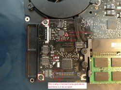
I got a 2008 Macbook unibody aluminium A1278, this computer was literally smashed against something, all parts of the housing are bent and full of bumps, it was free, so its a chalange to see if i can get it running. Of course Display is broken in pieces, about the main board, all seems fine, just a little piece broken at a ground point as u can see in the picture attached. I cant see anything cracked or broken anywhere else.

img4250y.jpg


When i connect the magsafe, i will get a green light, if i put the battery (a bit bent too so im not sure if its good or not) the magsafe light will turn orange, and will remain orange for about 10 minutes, then will go back to green.

But pressing the power button nothing happens, i read some post talking about the pins in the keyboard connector that belong to the power button, tryed to short them but all i get is a little movement from the fan, and the green light will go off and back on...
I dont have the power adaptor for this mac, but im using a adapter from a macbook pro 15", im not sure if its the 65w or 85w, text is all faded.

So my questions are, what else can i try to see if this board is still salvageable?

Do i need a working battery in order to start it up? Right now the main board is out of the bent case only with the fan attached and the bottom speaker and 4gb of RAM installed.

Thanks for any help
 

ace2000

macrumors newbie
Feb 3, 2013
23
0
finally got my iMac working so I'm back lol, ive replaced the R6995 and R6996 and the 47 ohm resistor and now I have G3HOT :D thanks cmdrdata ,so try to power it on and still nothing :( so I try the SMC bypass and the fan kicks in, first time i've heard it run so well pleased lol, I don't have a chime or any display but that could do with having a bit of corrosion on the WLED driver chip and 2 pins of the LVDS connector (I will read the other thread about this) but i dont want to get to that part if I have other work to do (it might not be worth it perhaps) I only get a dim green LED on the magsafe and no charging ( I have no output on the battery so assume its fully depleted) where should i start checking to at least get it fired up off the button (SMC good)? so i know if its worth progressing to the display problems....Thanks very much Justin...
 

ace2000

macrumors newbie
Feb 3, 2013
23
0
just re reading the entire thread now that I have sorted the G3HOT.
It maybe that all it needs apart from the screen issue is a new battery? because I get 12v ish at the 3vcc battery pins (on logic board) but when i plug in battery this goes to 0.12v and also I get the 3.4v at pin 12 of the charger IC,
So should I get a normal boot i.e. without SMC bypass if I replace battery?

thanks again Justin..
 

ace2000

macrumors newbie
Feb 3, 2013
23
0
sorry also just noticed that if a plug the battery connector in and back out again the MBP starts with quite normal fan but if i plug it back in it shuts down ?
 

cmdrdata

macrumors 6502
Jun 10, 2011
377
2
Dallas, Texas, USA
just re reading the entire thread now that I have sorted the G3HOT.
It maybe that all it needs apart from the screen issue is a new battery? because I get 12v ish at the 3vcc battery pins (on logic board) but when i plug in battery this goes to 0.12v and also I get the 3.4v at pin 12 of the charger IC,
So should I get a normal boot i.e. without SMC bypass if I replace battery?

thanks again Justin..

The system should be able to start with 1) just battery, if the battery is good, 2) just magsafe, with LED green, or 3) magsafe and battery.

In case #3, LED should be green if battery is fully charged or not present. In this state, the system works fully under magsafe power only. FET that gates battery power (I think Q7055) will be turned off. Alternately, if battery bad/dead/in-self-shutdown-protection-mode, the LED will also be green. The MBP power status from Apple menu will say "no battery".

If battery is somewhat depleted, LED will turn orange to indicate charging activity. When charging is complete, Q7055 will be turned of, thus powering the system entirely from magsafe. Magsafe is powering the system as well as supplying charging current to the battery.

I still don't have an explanation of what a dim green LED means. Maybe Dadioh or others have a clue.
 

Techkat

macrumors member
Jan 23, 2013
33
0
Paso Robles, California
See the attached "example" schematic from my Mid2009 MBP. ALL_SYS_PWRGD is an "OR-ed" signal of several power supply status. If it is low, then one of that power supply is probably not working, and you have to determine why. By this I mean go the respective supply and check the actual output line itself (not the status lines because it will logic zero due to the dragging down by the bad status) to see of the respective supply is putting out the correct voltage.

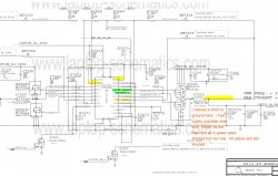
Well HI Commander, Are You Back? Did you have a nice trip? I did some checking out while you were gone. I am posting a pic of what I did find. I found a short to ground at L7220 and started tracing it out. I couldnt find any shorted components unless maybe u7200 is bad? But look on picture I post. I had short to ground on all items highlighted but after I had hubby unsolder side 1 of L7220 the areas highlighted in green are not shorted anymore. Just the ones in Yellow. What are these xw7201 thru xw7205 they show on schematic and boardview but you cant really test. Are they like a fusible link? Well let me know your thoughts. Thank you
 

Attachments

  • LB# 820-2530 schematic diagram u7200 2_Page_1.jpg
    LB# 820-2530 schematic diagram u7200 2_Page_1.jpg
    888.3 KB · Views: 8,765

cmdrdata

macrumors 6502
Jun 10, 2011
377
2
Dallas, Texas, USA
Well HI Commander, Are You Back? Did you have a nice trip? I did some checking out while you were gone. I am posting a pic of what I did find. I found a short to ground at L7220 and started tracing it out. I couldnt find any shorted components unless maybe u7200 is bad? But look on picture I post. I had short to ground on all items highlighted but after I had hubby unsolder side 1 of L7220 the areas highlighted in green are not shorted anymore. Just the ones in Yellow. What are these xw7201 thru xw7205 they show on schematic and boardview but you cant really test. Are they like a fusible link? Well let me know your thoughts. Thank you

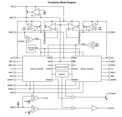
Yes I am back home. Based on what you shown, yes I think your 3.3v power supply is bad and it is possible that U7200 is bad for this reason: Look at VREG3, TONSEL, and C7270. I searched for 5V3V3S3_REG3 on the entire schematic and this signal doesn't go anywhere but there, so the fact that they measured short to ground to me means the chip has burned out. Temporarily remove C7270 and see if VREG3 is still shorted to ground. If it is, then I see no reason how it could be shorted to GND as it doesn't go anywhere else. See block diagram of U7200 attached. Internally, I think the FET output closest to VREG3 is shorted.
 

Attachments

  • Screen Shot 2013-02-13 at 9.53.27 PM.png
    Screen Shot 2013-02-13 at 9.53.27 PM.png
    68.9 KB · Views: 513

Techkat

macrumors member
Jan 23, 2013
33
0
Paso Robles, California
Yes I am back home. Based on what you shown, yes I think your 3.3v power supply is bad and it is possible that U7200 is bad for this reason: Look at VREG3, TONSEL, and C7270. I searched for 5V3V3S3_REG3 on the entire schematic and this signal doesn't go anywhere but there, so the fact that they measured short to ground to me means the chip has burned out. Temporarily remove C7270 and see if VREG3 is still shorted to ground. If it is, then I see no reason how it could be shorted to GND as it doesn't go anywhere else. See block diagram of U7200 attached. Internally, I think the FET output closest to VREG3 is shorted.

Yes Here is the only place they go.

sorry you have to click on it to see it better. the the line thats white goes all over the board. I checked each component and unless I'm not doing it right there are none shorted. I will do what you are asking above now and see what I get. Thank you
 

Attachments

  • LB# 820-2530 schematic diagram u7200 2_Page_2.jpg
    LB# 820-2530 schematic diagram u7200 2_Page_2.jpg
    241.4 KB · Views: 690

young88a

macrumors newbie
Feb 9, 2013
17
0
Macau
as a update to my post, today i was able to try a good battery on my board, same situation, after connecting the magsafe, the light was green, no oragen cause this battery was fully charged. I tried to do a SMC bypass, and after that, no more green light, also the board will not start same as before.

My concern is why now theres no light on the magsafe? if i connect it to another macbook, and then connect to this board the light will go on, and slowly fades aways until its off, then another try the light was orange, even without a battery ....

Did the magsafe board went bad or was already bad before??
 

cmdrdata

macrumors 6502
Jun 10, 2011
377
2
Dallas, Texas, USA
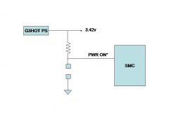
Powering up logic board from test pad

Attached is a logic diagram of powering up an MB/MBP logic board. I think a few people that come across this forum mistakenly think that temporarily shorting two pad (one measured 3.4v and the other ground) will command the system to power up. This is NOT a good thing unless you know for certain that these are indeed the "correct" power on pads. As you see in the diagram, the correct power on pads do measure 3.4v and GND, but the 3.4v measured is through a pull-up resistor, thus when you temporarily short the 2 pads, it send a 0 volt pulse signal to the SMC telling it to start the system. Doing this will not damage the system since the resistor will limit the current draw from G3HOT power supply. Shorting the G3HOT supply output directly to ground even for a fraction of a second on the other hand will draw unlimited current from that supply and thus may damage the power supply, resulting in loss of 3.42v source. So make sure you know what you are doing.
 

Attachments

  • PowerOn.jpg
    PowerOn.jpg
    9.5 KB · Views: 371

Techkat

macrumors member
Jan 23, 2013
33
0
Paso Robles, California
Some History and A WHOLE LOT OF APPRECIATION!!!

Yes I am back home. Based on what you shown, yes I think your 3.3v power supply is bad and it is possible that U7200 is bad for this reason: Look at VREG3, TONSEL, and C7270. I searched for 5V3V3S3_REG3 on the entire schematic and this signal doesn't go anywhere but there, so the fact that they measured short to ground to me means the chip has burned out. Temporarily remove C7270 and see if VREG3 is still shorted to ground. If it is, then I see no reason how it could be shorted to GND as it doesn't go anywhere else. See block diagram of U7200 attached. Internally, I think the FET output closest to VREG3 is shorted.

Hi Commander,

Ok I had hubby remove the Capacitor C7270 and all points on U7200 have not changed as far as short to ground.

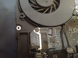
Here is a little history of board if it helps. I received it with stated liquid damage. I opened up bottom to look when I got it. I noticed that the power fet Q7001 was damaged via corrosion of pins 1,2,3 only 3 was still connected and the joints looked like they were corroded Board was pretty clean otherwise so I'm guessing that the board has been removed previously and cleaned. I still pulled it to do that myself and I noticed that the two screws on left side holding board on were basically welded to board ( see picture) So I had to remove the board with the frame on that side still attached. All in all the board looked pretty clean but there was some mold on U7200 on the right side. I cleaned with the 99% alcohol and let dry very good overnight. The next day I took some readings ( voltages and continuity) in all the places I usually do, which I learned from this forum. (ex. Fuses F6905, F7000 For both cont and voltage which were 16.85 and 12.65 respectively. I checked the fets Q7000 and & 7001 all voltages on pins looked good. checked for voltages at Keyboard connector J5713 especially pins 5 looked good at 3.42 v, I then checked the Jump pad above for 3.4 and had 3.42 I then went to batt connector J6950 and checked pins 4 and 6 for 3.42v all looked good) So I tried to start wouldn't start. Then had hubby replace the Q7001 and checked all voltages again and looked good. IT wouldn't start and that's when you asked me to check ALL_SYS_PWRGD and I found those voltages not present. I don't know if this will help or not. Thank you for all the Help IT IS SO MUCH APPRECIATED !!!!

P.S. I always photograph board as recieved for future reference this is that area. as I received it.
 

Attachments

  • IMG_1844.jpg
    IMG_1844.jpg
    2.6 MB · Views: 1,213
  • IMG_1785.JPG
    IMG_1785.JPG
    2.6 MB · Views: 528
Last edited:

Techkat

macrumors member
Jan 23, 2013
33
0
Paso Robles, California
Hi Commander,

Ok I had hubby remove the Capacitor C7270 and all points on U7200 have not changed as far as short to ground.

Here is a little history of board if it helps. I received it with stated liquid damage. I opened up bottom to look when I got it. I noticed that the power fet Q7001 was damaged via corrosion of pins 1,2,3 only 3 was still connected and the joints looked like they were corroded Board was pretty clean otherwise so I'm guessing that the board has been removed previously and cleaned. I still pulled it to do that myself and I noticed that the two screws on left side holding board on were basically welded to board ( see picture) So I had to remove the board with the frame on that side still attached. All in all the board looked pretty clean but there was some mold on U7200 on the right side. I cleaned with the 99% alcohol and let dry very good overnight. The next day I took some readings ( voltages and continuity) in all the places I usually do, which I learned from this forum. (ex. Fuses F6905, F7000 For both cont and voltage which were 16.85 and 12.65 respectively. I checked the fets Q7000 and & 7001 all voltages on pins looked good. checked for voltages at Keyboard connector J5713 especially pins 5 looked good at 3.42 v, I then checked the Jump pad above for 3.4 and had 3.42 I then went to batt connector J6950 and checked pins 4 and 6 for 3.42v all looked good) So I tried to start wouldn't start. Then had hubby replace the Q7001 and checked all voltages again and looked good. IT wouldn't start and that's when you asked me to check ALL_SYS_PWRGD and I found those voltages not present. I don't know if this will help or not. Thank you for all the Help IT IS SO MUCH APPRECIATED !!!!

P.S. I always photograph board as recieved for future reference this is that area. as I received it.

Now that I see picture knowing what I know, No wonder its shorted out.

Ill tell you why I do this... I had a customer whose Macbook Pro I fixed and I just fell in love with it. They have come so far from the old MacSe I had. I looked and they are pricey, so I figured maybe if I worked and repaired some that eventually I could get myself one.
 

young88a

macrumors newbie
Feb 9, 2013
17
0
Macau
I would like to make a update, i tested the part near the magasafe connector and it have 14.8 V and at the G3Hot have 3,35 V, is this a good sign?

Please check the picture.

img4306e.jpg
[/URL][/IMG]
 

cmdrdata

macrumors 6502
Jun 10, 2011
377
2
Dallas, Texas, USA
I would like to make a update, i tested the part near the magasafe connector and it have 14.8 V and at the G3Hot have 3,35 V, is this a good sign?

Please check the picture.

URL]

Yes, that's good. 14.8 is a bit low. and G3HOT at 3.35 is also a bit low, but usable. Check for 12v at the white block just above the SODIMM. You should see 12v there with just the magsafe, and just the battery.

----------

Now that I see picture knowing what I know, No wonder its shorted out.

Ill tell you why I do this... I had a customer whose Macbook Pro I fixed and I just fell in love with it. They have come so far from the old MacSe I had. I looked and they are pricey, so I figured maybe if I worked and repaired some that eventually I could get myself one.

Before installing the new U7200/TPS51125, check the resistance of L7220 pins 1 and 2 to ground. It should be much more than R= V/A = 3.3v/4A. If you get less or still shorted, then you've got to trace that too.
(4A is the maximum design rating of that supply, and all circuit should never draw the max amount).
 

young88a

macrumors newbie
Feb 9, 2013
17
0
Macau
Yes, that's good. 14.8 is a bit low. and G3HOT at 3.35 is also a bit low, but usable. Check for 12v at the white block just above the SODIMM. You should see 12v there with just the magsafe, and just the battery.

----------

Thanks a lot for your reply.

What is the white block you referring to? Is it that one with a "+" and some numbers (330e88) ?
Anyway i measured that one, red tip on the plus side and black tip on a ground point, that one just above the SODIMM shows 0V, all the others in the board show 12.48V.

I dont have right now a good working battery to test the system. The battery form this macbook wont charge on a good working macbook same model. Anyway this battery have 5 pins, any tips on how to measure them? I dont know if its important, but the magsafe i was using was the 45W version form a Macbook Air.

Here is a updated pictures with the measurements i got:

img4306dm.th.jpg
[/URL][/IMG]

img4309t.jpg
[/URL][/IMG]

Any others i need to measure?
 
Last edited:

cmdrdata

macrumors 6502
Jun 10, 2011
377
2
Dallas, Texas, USA


Thanks a lot for your reply.

What is the white block you referring to? Is it that one with a "+" and some numbers (330e88) ?
Anyway i measured that one, red tip on the plus side and black tip on a ground point, that one just above the SODIMM shows 0V, all the others in the board show 12.48V.

I dont have right now a good working battery to test the system. The battery form this macbook wont charge on a good working macbook same model. Anyway this battery have 5 pins, any tips on how to measure them? I dont know if its important, but the magsafe i was using was the 45W version form a Macbook Air.

Any others i need to measure?


Ignore my question. I was thinking of an MBP13 layout when I asked the question. On that one. near the SODIMM is a fuse that protects the power draw from magsafe or battery for their 12v. What you had measured are mostly polarized capacitors, hence the white bar and + markings.
 
Last edited:

Techkat

macrumors member
Jan 23, 2013
33
0
Paso Robles, California
Yes, that's good. 14.8 is a bit low. and G3HOT at 3.35 is also a bit low, but usable. Check for 12v at the white block just above the SODIMM. You should see 12v there with just the magsafe, and just the battery.

----------


Before installing the new U7200/TPS51125, check the resistance of L7220 pins 1 and 2 to ground. It should be much more than R= V/A = 3.3v/4A. If you get less or still shorted, then you've got to trace that too.
(4A is the maximum design rating of that supply, and all circuit should never draw the max amount).

Hi commander,

Without the L7220 connected (I had hubby pull up to check the other day) but in that spot I have 10.3 ohms to ground on pin 2 and on pin 1 I have 10.6 ( i just put meter on spot they are supposed to be.

Using the audible on tester for continuity I have short to ground on 2 and none on 1. When I first noticed the short to ground it was at this location and I asked hubby to pull up pin 1 (which looking at the board is actually the left side.) you can see pic in post 1356. FYI we havent done anything with u7200 I know that's going to be hard to do.
 

Giuly

macrumors 68040
QZGZmc0.jpg


Well, I have good news and bad news. After extracting the charger IC, it came to light that the two traces and pads are gone. Luckily they connect to the capacitor underneath U7000, so hopefully I'll get away with bluewiring them.

With the ISL6259A removed, the charger now also shows a solid green light, so at least the MagSafe and DCIN board, as well as the SMC are still good.

I'm now waiting for the new ISL6259A. One quick question, though: UGATE and LGATE were both logical Zero, so they should've been open, shouldn't they? Could it be that because of defective MOSFETs, they remained shut, the ISL6259A didn't sense a higher voltage on the PHASE line and thus caused the charger to go dim green, as it appeared to the IC that it didn't deliver any power?
 

young88a

macrumors newbie
Feb 9, 2013
17
0
Macau
One more update,

I measure the volts in the battery connector and the values i got are on the attached pic.

There is a small white fuse near the battery level connector, and seems ok, have 12.48v

Any tips of other fuses i should test?

Thanks guys, im learning a lot from this forum, but really need some more guidance.

img4320d.jpg
[/URL][/IMG]

Right now i still have just a very dim green light on the magsafe, and bridging pins 39 and 5 at the keyboard connector still makes the fan gives a little flick, but no startup of the board. Pressing power button also doesnt do anything, not even the little fan movement.
 

cmdrdata

macrumors 6502
Jun 10, 2011
377
2
Dallas, Texas, USA
Hi commander,

Without the L7220 connected (I had hubby pull up to check the other day) but in that spot I have 10.3 ohms to ground on pin 2 and on pin 1 I have 10.6 ( i just put meter on spot they are supposed to be.

Using the audible on tester for continuity I have short to ground on 2 and none on 1. When I first noticed the short to ground it was at this location and I asked hubby to pull up pin 1 (which looking at the board is actually the left side.) you can see pic in post 1356. FYI we havent done anything with u7200 I know that's going to be hard to do.

Impedance of around 10 Ohm on pin L7220-2 is probably normal. With L7220 removed, pin1 should have much higher impedance since it is connected to to the push-pull FETs and feedback pin of U7200. This is well within the loading of 3.3v supply (3.3v/10A = 330mA). In reality the active loading will be more than that but certainly no where near the design limit of 4A. Audible tester cannot really distinguish low resistance value from a short, so that's not a good way to check for shorts except for quick test followed by actual ohmmeter reading.

----------

One more update,

I measure the volts in the battery connector and the values i got are on the attached pic.

There is a small white fuse near the battery level connector, and seems ok, have 12.48v

Any tips of other fuses i should test?

Thanks guys, im learning a lot from this forum, but really need some more guidance.

URL]


Right now i still have just a very dim green light on the magsafe, and bridging pins 39 and 5 at the keyboard connector still makes the fan gives a little flick, but no startup of the board. Pressing power button also doesnt do anything, not even the little fan movement.

As mentioned, I don't have your schematic, but reading 12.48v on the fuse is good, meaning the magsafe power is making it that far. Do you have have G3HOT 3.42v? Your battery reading is low, I think the battery is depleted and in need of a charge. In MBP there is a power FET labeled Q7055 that controls power from battery to the system (probably in our picture it is the one next to the fuse) as well as allowing charging current to the battery. If that is the same as in older MBP, pin 123 are usually tied together and should have almost the same voltage as pin 5. Pin 4 should have some positive voltage somewhere around 3-7v. (Just a guess though).
 

colinm9

macrumors newbie
Feb 17, 2013
8
0
Canada
White Screen

Fantastic info here. I don't see my problem but apologies if it's already there.
MBP 13, 2010.
Boots to white screen only. Chimes and loads OS normally. Screen brilliance and keyboard backlight can be adjusted and seem to respond to ambient light changes.
Works perfectly fine on external (TV). GPU is detected properly in system info. It's not the display or LVDS cable - I hooked the assembly up to another machine and it's fine.
No liquid or other damage that I can see. I can post good close ups of areas of the logic board if anyone can help?
Thanks in advance!
Colin
 

young88a

macrumors newbie
Feb 9, 2013
17
0
Macau
Impedance of around 10 Ohm on pin L7220-2 is probably normal. With L7220 removed, pin1 should have much higher impedance since it is connected to to the push-pull FETs and feedback pin of U7200. This is well within the loading of 3.3v supply (3.3v/10A = 330mA). In reality the active loading will be more than that but certainly no where near the design limit of 4A. Audible tester cannot really distinguish low resistance value from a short, so that's not a good way to check for shorts except for quick test followed by actual ohmmeter reading.

----------


As mentioned, I don't have your schematic, but reading 12.48v on the fuse is good, meaning the magsafe power is making it that far. Do you have have G3HOT 3.42v? Your battery reading is low, I think the battery is depleted and in need of a charge. In MBP there is a power FET labeled Q7055 that controls power from battery to the system (probably in our picture it is the one next to the fuse) as well as allowing charging current to the battery. If that is the same as in older MBP, pin 123 are usually tied together and should have almost the same voltage as pin 5. Pin 4 should have some positive voltage somewhere around 3-7v. (Just a guess though).

Thanks CMDRDATA, yes i have 3.35v at G3HOT, and in that picture, theres no battery connected, im not worrying about the battery as the one i have is damaged and not charging even on a good system. Waiting for Dadioh insight, i think he knows this board well :)

Ill try today with a 85w power adaptor.
 

young88a

macrumors newbie
Feb 9, 2013
17
0
Macau
One more update.

Today i tested with a 85w adaptor, and a good battery. Shorting pins 4 and gnd on the keyboard connector, the fan will spin, but will stop when i stop doing it.

Only with the battery connected, same thing, shorting pins 4 and gnd, fan spins, only with power adaptor, just give a little flick, both battery and power adaptor fan also spins, but i dont think the board starts up because it will spin only while im bridging those pins.

Any ideas?
 

Techkat

macrumors member
Jan 23, 2013
33
0
Paso Robles, California
Impedance of around 10 Ohm on pin L7220-2 is probably normal. With L7220 removed, pin1 should have much higher impedance since it is connected to to the push-pull FETs and feedback pin of U7200. This is well within the loading of 3.3v supply (3.3v/10A = 330mA). In reality the active loading will be more than that but certainly no where near the design limit of 4A. Audible tester cannot really distinguish low resistance value from a short, so that's not a good way to check for shorts except for quick test followed by actual ohmmeter reading.

----------

Hi Commander,

Ok I measured the pins you asked I just wanted to note that the L7220 and the C7270 are both pulled with the results listed below.

Thank you so much for your patience. okay remeasuring with just ohms L7220 pin 1 is 7.15 k ohm and 2 is 10 ohm

After you telling me about not using the audible I went back and measured pins 4 and 8 on U7200 to ground and they are both 1.8 M ohms to ground. Remember though you asked me to remove cap C7270 in post 1357.

So since I kind of led this thing astray. You had asked me to trace out the ALL_SYS_PWRGD showing no voltage. I was having a problem though understanding. I did a search for those lines or nets to all those you circled and I came up short I had checked the page numbers next to them but the lines don't have the same wording so I'm not sure which ones to check. So when you went to Carlsbad I just starting checking things like short to ground but with the audible. I do hear you though you are saying that at first just running around and checking the board out you can use the audible but if you do find something check with ohms to verify.

Thank you.
 
Register on MacRumors! This sidebar will go away, and you'll see fewer ads.