Become a MacRumors Supporter for $50/year with no ads, ability to filter front page stories, and private forums.

AlohaMac

macrumors newbie
Mar 5, 2013
6
0
Nobody an Idea about my A1342 LB? Or did i chime in just too rude...:confused:;)

@Dadioh/Rossman: What kind of stereo Microscopes are you using so far? (magnification factor) Is 20x enough to exactly see what i am doing, f.e. if i'd like to solder a 0402 part?

Sadly my Weller PU81 has decided to die, (yes, also Weller isn't made to last till infinity, however it lasted for years and years and years... :))
I was thinking about purchasing a new one, but somewhere read that Dadioh is very excited of a solder station (couldn't find the post again, i remember the name of it begun with a "M"). Would that may be an alternative to my died Weller PU81?

Cheers from Germany, Aloha
 

Dadioh

macrumors 65816
Original poster
Feb 3, 2010
1,123
36
Canada Eh?
Nobody an Idea about my A1342 LB? Or did i chime in just too rude...:confused:;)

@Dadioh/Rossman: What kind of stereo Microscopes are you using so far? (magnification factor) Is 20x enough to exactly see what i am doing, f.e. if i'd like to solder a 0402 part?

Sadly my Weller PU81 has decided to die, (yes, also Weller isn't made to last till infinity, however it lasted for years and years and years... :))
I was thinking about purchasing a new one, but somewhere read that Dadioh is very excited of a solder station (couldn't find the post again, i remember the name of it begun with a "M"). Would that may be an alternative to my died Weller PU81?

Cheers from Germany, Aloha

Well I got a really good deal on eBay on a Metcal SP200. I think OKI has bought Metcal and I don't think they make the SP200 anymore but if you can find a good deal, even on a used one, it is probably better than a new cheaper brand. The Metcal heats up almost instantly and has very precise temperature control at the tip. Lots of different tips available too.

http://canada.newark.com/metcal/sp200-11/solder-station/dp/04M4605

As far as microscopes go, I bought from these guys since I am in Canada. Huge selection and good prices. You can probably find an equivalent place in the US.

You want a good boom stand, a circular LED light, and a 0.5X Barlow lens to increase the distance under the microscope so you can get a soldering iron in there.

http://www.ebay.ca/itm/Dual-bar-Boo...n_2&hash=item1c2b1b0f35&_uhb=1#ht_4445wt_1041
 

Southwest

macrumors newbie
Feb 22, 2013
12
0
No Charge

New to this forum:
Just a few question that I hope someone with more experience than I might be able to point me in the right directions.

I received an A1278 13” mid 2010 i5 macbook with what looked like minor water damage. Tested logic board without the keyboard connected and it booted fine.
Replaced keyboard and everything works great again.

The issue is when charger is attached there is neither a green or orange light on charger. When booted in the upper right of the display shows 41% and the battery indicator symbol shows the charger is connected. As long as you have the charger attached the battery level does not change either up or down.The system will boot with only battery, but will not with just the charger

System Report shows Charge remaining: 2339 Fully Charged: No Charging: No
Full: 5664 Cyc: 3 Condition: Normal Battery Installed: Yes Amp: 0 Voltage: 11402

AC Charger info: Connected: Yes Charging: No Have tried a couple of magsafe chargers, replaced the magesafe also.
SMC has been tried
Logic board 820-2879B

Have full setup for testing voltages. I have the board Schematic and board view need to know what to look for and where.
Thanks in advance for any help!!!
 

naKruul

macrumors newbie
Dec 25, 2011
25
0
and i'm like: WTF?

Hey Guys, awesome thread i have to say. I managed to read through most of the 57 pages phew
A while ago i was able to fix the WLED driver on my 2011 13“ MBP with some help by dadioh.

I recently picked up a 2009 Macbook Pro 5,5 13“ 2,26 jigohertz :D It is supposed to have a liquid spill damage, although i did not find any residue on the board. It seems to have been cleaned before. When it arrived it was in partially working condition, meaning:

Magsafe charging OK
Power OK
Battery OK
HDD Spinup
ODD Spinup
Fan Spinup

But that was it. No further booting, screen stays black, SIL glowing

I disassembled the unit and totally subermerged it in isoprop and scrubbed it. After reassembling still the same. I tried the SMC bypass/debug method and evetually the unit booted. Everything seems kinda normal. So shutdown. Power the unit back on and this time it boots right into OSX 10.8.2 without a hassle. Every single piece of periphery working like a charm. But here it comes:

When closing the lid the mbp enters standby mode with no problems. But after reopening it does not come alive. The HDD spins up, fan is spinning and the SIL comes on solid. I have to hard shutdown the unit and repower it. So there comes the screen mit the progress bar and I am in OSX right away. Now it’s getting weird: After like 10 seconds the date and time changes to a random count. I had everything from 1999 to 2043... WTF?! So then i go to system prefs – date and time – immediate sync with apple time, everything back to normal. The above behaviour also happens when enering hibernation or when the unit goes so standby by itself.
I don’t get it. Tried SMC, PRAM, EFI Reset to no avail.

Another odd thing i noticed is when the device comes „alive“ after standby or whatsoever and the SIL is on, it is sensitive to ambient light changes, meaning if i cover the ALS with my finger the SIL dims?!

Anyone has a guess? Btw: this is a clean install of 10.8.2 maybe i should give leopard or SL a try?
 

Dadioh

macrumors 65816
Original poster
Feb 3, 2010
1,123
36
Canada Eh?
New to this forum:
Just a few question that I hope someone with more experience than I might be able to point me in the right directions.

I received an A1278 13” mid 2010 i5 macbook with what looked like minor water damage. Tested logic board without the keyboard connected and it booted fine.
Replaced keyboard and everything works great again.

The issue is when charger is attached there is neither a green or orange light on charger. When booted in the upper right of the display shows 41% and the battery indicator symbol shows the charger is connected. As long as you have the charger attached the battery level does not change either up or down.The system will boot with only battery, but will not with just the charger

System Report shows Charge remaining: 2339 Fully Charged: No Charging: No
Full: 5664 Cyc: 3 Condition: Normal Battery Installed: Yes Amp: 0 Voltage: 11402

AC Charger info: Connected: Yes Charging: No Have tried a couple of magsafe chargers, replaced the magesafe also.
SMC has been tried
Logic board 820-2879B

Have full setup for testing voltages. I have the board Schematic and board view need to know what to look for and where.
Thanks in advance for any help!!!

Have you checked pin 14 on the charger IC? That will be 3V when charger is happy. 0V indicates a charger circuit issue. I posted some info a few pages back with where to measure pin 14. Although that is for the Core2Duo board. Your i5 layout may have a different orientation on the charger IC but check for the mark for pin 1 on the IC and then go counter clockwise around to get to pin 14.
 

l.a.rossmann

macrumors 65816
May 15, 2009
1,097
372
Brooklyn
Thanks for the advice. When replacing a connector on a macbook board do you have to preheat the board and do you use a hot air station or the solder iron ?

I try to preheat all the time. It's just good practice. A fan or speaker connector isn't going to have as much preheating required as an LVDS connector.

You need a hot air station to get it off, and a soldering iron to get it on. The hot air will melt the plastic inside the connector. I am unsure if this is due to my lack of talent or if it's just reality, but there's no way for me to use hot air to put a connector back on the board. The plastic melts, the pins shrivel up and move around to where the connector is useless, as they move around inside the melting plastic. It's just bad. I use a hakko fr-801 to remove the old connector with one of those rectangular [] shaped nozzles opposed to the o shaped nozzle, a hakko 808 to remove all the old solder, clean it with a kester 951 pen, put the new connector in place. I place it on the board with kapton tape, then solder the ends of it. I remove the kapton tape and solder each individual pin, and pray that I don't **** it up. Sometimes the pins get soldered together and it is almost impossible to get the little solder crud out. Amtech flux for BGA rework is great for this, I clump it over the crap and do my best to get the solder spread back across 1 o2 2 solder pads.

Using a hot air station on a connector will melt it.. they're made of plastic, besides the pins. Gotta love this crap. Remove a fan or LVDS connector and you'll see what I mean. **SOMETIMES** it'll actually come off without melting into pieces. If you really do your job preheating it and remove the connector with just the amount of heat needed to remove it, and don't heat the board or the connector a degree over, it'll only come off partially melted. Most of my LVDS connectors come off looking toasted and ****ed up.
 

l.a.rossmann

macrumors 65816
May 15, 2009
1,097
372
Brooklyn
Nobody an Idea about my A1342 LB? Or did i chime in just too rude...:confused:;)

@Dadioh/Rossman: What kind of stereo Microscopes are you using so far? (magnification factor) Is 20x enough to exactly see what i am doing, f.e. if i'd like to solder a 0402 part?

Sadly my Weller PU81 has decided to die, (yes, also Weller isn't made to last till infinity, however it lasted for years and years and years... :))
I was thinking about purchasing a new one, but somewhere read that Dadioh is very excited of a solder station (couldn't find the post again, i remember the name of it begun with a "M"). Would that may be an alternative to my died Weller PU81?

Cheers from Germany, Aloha
I do not have a microscope which is why I perform the ghetto soldering tactic at the end of this video to "correct" any potential bad soldering in the QFN. I do a particular poor job because where my elbow would usually go as I sit over the board, there's a tripod and a camera, which makes this near impossible since I can't hover over the chip while sitting as I like to.

I should have a microscope considering my profession. I have no excuse for my shameful lack of tools. :( I use a micro lens on a nikon D3100 camera to double check my work in realtime. Yes, I really need to buy a microscope. I do three things at the end.

a) Visual inspection up close.

b) Go around the chip with flux, solder, and a chizeled off tip that fits under the package after work.

c) Touching the chip to ensure it does not get hotter than the rest - to confirm the middle pad is soldered properly.

On 0402 and 0603, I don't need a microscope. My hand is unsteady - I am limited by my hands long before I will be limited by my sight. I believe you can do a good 0402 job without a microscope. It's when you get into LVDS connectors that a microscope is welcome. With 0402 a microscope isn't what I need, a leash that attaches to the component so it doesn't run away would be much more valuable. :)

I turn it on, and also forgot to put in the video - touch the QFN to check its temperature. It should not get hotter than any other IC on the board. If it gets noticeably hotter, the center pad is not making proper contact.

As for equipment, I use a Hakko 936, Hakko FR-801, and Hakko 808. You can substitute much cheaper Aoyue stuff, but I got tired of it dying. There is nothing worse than being 2 minutes away from billing $200 and your **** dying.
 
Last edited:

Southwest

macrumors newbie
Feb 22, 2013
12
0
Have you checked pin 14 on the charger IC? That will be 3V when charger is happy. 0V indicates a charger circuit issue. I posted some info a few pages back with where to measure pin 14. Although that is for the Core2Duo board. Your i5 layout may have a different orientation on the charger IC but check for the mark for pin 1 on the IC and then go counter clockwise around to get to pin 14.

Located pin 14 and it has 3.25v, all fuse checked out also. Any suggestions for the next check. Battery has been on charger for 4hrs and no change from the 41% charge.
 

GlassOgnion

macrumors member
Sep 10, 2003
83
0
Quebec, Canada
@ l.a.rossmann

Just bought this microscope to check my boards. Unlike most microscopes who only have 2" or 3" clearance under the lens this one has 9" working space so you can work on the board under the lens with a solder iron without problem. It's a 10X and 20X so plenty magnification for repair and inspection. Very good quality for a $200 microscope with a boom.

http://www.microscopenet.com/boom-stand-binocular-stereo-microscope-10x20x-p-213.html


I do not have a microscope which is why I perform the ghetto soldering tactic at the end of this video to "correct" any potential bad soldering in the QFN. I do a particular poor job because where my elbow would usually go as I sit over the board, there's a tripod and a camera, which makes this near impossible since I can't hover over the chip while sitting as I like to.

I should have a microscope considering my profession. I have no excuse for my shameful lack of tools. :( I use a micro lens on a nikon D3100 camera to double check my work in realtime. Yes, I really need to buy a microscope. I do three things at the end.
 

mushyppeaz

macrumors newbie
Jan 4, 2010
6
0
Oxford
MAcbook air 11" 1370 fuse location

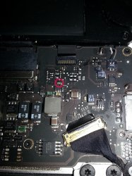
Hi all. I have done the classic relpacing the screen without disconnecting the battery. I have read through the posts but am not 100% on which fuse it is that is blown. in the photo attached is it the one I have circled with an N on it?

I have not tested it but am in the process just to double check its working if there is a reading not if it is 0.

I have bought these "Avx Capacitor 0402 X5R 25V 100Nf 04023D104Kat2A" link attached, will they do the job? they seem smaller than the one with an N on it..

All help is much appreciated!

:)
 

Attachments

  • MAcbook_air_backlight_fuse.jpg
    MAcbook_air_backlight_fuse.jpg
    1.9 MB · Views: 1,063

naKruul

macrumors newbie
Dec 25, 2011
25
0
Hi all. I have done the classic relpacing the screen without disconnecting the battery. I have read through the posts but am not 100% on which fuse it is that is blown. in the photo attached is it the one I have circled with an N on it?

I have not tested it but am in the process just to double check its working if there is a reading not if it is 0.

I have bought these "Avx Capacitor 0402 X5R 25V 100Nf 04023D104Kat2A" link attached, will they do the job? they seem smaller than the one with an N on it..

All help is much appreciated!

:)

if you measure 0 the fuse is ok

what you bought is not a fuse but a capacitor.
 

mushyppeaz

macrumors newbie
Jan 4, 2010
6
0
Oxford
Macbook air 11" 1370 fuse location

Thanks! so what size fuse do I need, and am I right in thinking its the one with an N on it?

cheers!
 

naKruul

macrumors newbie
Dec 25, 2011
25
0
i don't have schematics at hand, but the backlight fuses usually have a P, N or a dot as marking. so i guess that's the one you're looking for

you need a 32V 2Amp 0402 size fuse
 

Southwest

macrumors newbie
Feb 22, 2013
12
0
13" Mid2010

Sounds like the charger is happy if pin 14 is 3.4V. Now need to check downstream where that signal converts to the signal to the magsafe. See attachment. I don't have a logic board handy to show you where the devices are but one of them is backside near the magsafe connector IIRC. I would need to stare at a board to remember the other.

I have followed the trail to U6900 and U6901 here is what I have found on both. Finally something not up to par...need help for next test
U6900
1 = 0v
4 = 0v
5 = 0v
U6901
1 = 3.25v
2 = 3.25v
4 = 0v
5 = 0v
Still can't find why no charge will continue to follow trail...
 

AlohaMac

macrumors newbie
Mar 5, 2013
6
0
@Dadioh & Rossmann: Thank you very much for your detailed Answers!
The Metcal 200 Station seems to be a nice one, but at least it's not adjustable (ok, with different tips it is) but i think i will buy a controllable JBC Soldering station. Was looking around for soldering stations the last days, think thats just what i need (or just want?! :D).

The Microscopes posted seem to be quiet cheap, wow! May i give one of them a try, but first i need a soldering station again :)
For hot air i use a Aoyue 852, it's woking perfectly for about a year now, never had an issue with it... Maybe just luck.

Thanks very much for your advices!

Aloha
 

AlohaMac

macrumors newbie
Mar 5, 2013
6
0
Hey Folks, me again,

i have another "dead" Logicboard here, it's from a late 2008 Unibody 15" MBP (the one without Cardreader), PartNo.: 820-2532-A.
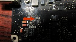
Just noticed while cleaning it up (has no spill damage, or at least i can't find any indication for a spill damage) that a small 0402 Part seems to be fried. In the pic attatched you can see it spotted by an arrow. Could that cause a dim green light at magsafe and no boot?

When i attatch the magsafe, i get a very, very, very dimm green light (almost not visible if not darken environment around), does not power up.

First i checked the 2 Fuses (near Magsafe and near battery connector), both seem to be fine though.

STOP, when no current is attatched to the board and i measure with my Multimeter appointed to 200 Ohms, shouldn't the Fuse give me 0? However, i measure about 0.1 on each... But with magsafe connected i can read current on both sides of each fuse. Is that ok? Sorry, i'm not an electronics wizard so any help is much appreciated...

Next i checked the 4th and 5th pin of the Keyboard connector, pin 4 gives 3.39V, pin 5 is about 3.32V. Is that right?

Any ideas would be great, i appeciate any help i could get.

Thanks for reading,
Aloha
 

Attachments

  • IMG_6106.JPG
    IMG_6106.JPG
    1.2 MB · Views: 1,503
Last edited:

Dadioh

macrumors 65816
Original poster
Feb 3, 2010
1,123
36
Canada Eh?
Hey Folks, me again,

i have another "dead" Logicboard here, it's from a late 2008 Unibody 15" MBP (the one without Cardreader), PartNo.: 820-2532-A.
Just noticed while cleaning it up (has no spill damage, or at least i can't find any indication for a spill damage) that a small 0402 Part seems to be fried. In the pic attatched you can see it spotted by an arrow. Could that cause a dim green light at magsafe and no boot?

When i attatch the magsafe, i get a very, very, very dimm green light (almost not visible if not darken environment around), does not power up.

First i checked the 2 Fuses (near Magsafe and near battery connector), both seem to be fine though.

STOP, when no current is attatched to the board and i measure with my Multimeter appointed to 200 Ohms, shouldn't the Fuse give me 0? However, i measure about 0.1 on each... But with magsafe connected i can read current on both sides of each fuse. Is that ok? Sorry, i'm not an electronics wizard so any help is much appreciated...

Next i checked the 4th and 5th pin of the Keyboard connector, pin 4 gives 3.39V, pin 5 is about 3.32V. Is that right?

Any ideas would be great, i appeciate any help i could get.

Thanks for reading,
Aloha

That part looks like a cap and it seems to be related to the Realtek sound circuit. Would need to see a schematic to be certain but I doubt it would be related to the charging circuit failure.

0.1ohms across a fuse is fine. What do you get when you touch the tips of the meter together? My meter usually shows about 0.4ohms so that is about best case you can ever expect. A fuse will either be a few ohms (Good) or Megaohms (Blown). Nothing in between.

For dim charge LED alsways start at charger IC pin 14. If that is not 3V then you will not get a green LED. If it is 3V then at least the charger is OK and the issue is between that signal and the magsafe connection. There are a few components to check there.

----------

I have followed the trail to U6900 and U6901 here is what I have found on both. Finally something not up to par...need help for next test
U6900
1 = 0v
4 = 0v
5 = 0v
U6901
1 = 3.25v
2 = 3.25v
4 = 0v
5 = 0v
Still can't find why no charge will continue to follow trail...

U6901 pin 5 is G3HOT so if you have 0V there you should be dead on the entire logic board?

Basically your AND gate U6901 has no power so the SMC_BC_ACOK signal is not passing through to U6900. Double check U6901 pin 5 and, if it is really 0V I think you need to check the solder connections on that device and replace.
 

naKruul

macrumors newbie
Dec 25, 2011
25
0
Hey Guys, awesome thread i have to say. I managed to read through most of the 57 pages phew
A while ago i was able to fix the WLED driver on my 2011 13“ MBP with some help by dadioh.

I recently picked up a 2009 Macbook Pro 5,5 13“ 2,26 jigohertz :D It is supposed to have a liquid spill damage, although i did not find any residue on the board. It seems to have been cleaned before. When it arrived it was in partially working condition, meaning:

Magsafe charging OK
Power OK
Battery OK
HDD Spinup
ODD Spinup
Fan Spinup

But that was it. No further booting, screen stays black, SIL glowing

I disassembled the unit and totally subermerged it in isoprop and scrubbed it. After reassembling still the same. I tried the SMC bypass/debug method and evetually the unit booted. Everything seems kinda normal. So shutdown. Power the unit back on and this time it boots right into OSX 10.8.2 without a hassle. Every single piece of periphery working like a charm. But here it comes:

When closing the lid the mbp enters standby mode with no problems. But after reopening it does not come alive. The HDD spins up, fan is spinning and the SIL comes on solid. I have to hard shutdown the unit and repower it. So there comes the screen mit the progress bar and I am in OSX right away. Now it’s getting weird: After like 10 seconds the date and time changes to a random count. I had everything from 1999 to 2043... WTF?! So then i go to system prefs – date and time – immediate sync with apple time, everything back to normal. The above behaviour also happens when enering hibernation or when the unit goes so standby by itself.
I don’t get it. Tried SMC, PRAM, EFI Reset to no avail.

Another odd thing i noticed is when the device comes „alive“ after standby or whatsoever and the SIL is on, it is sensitive to ambient light changes, meaning if i cover the ALS with my finger the SIL dims?!

Anyone has a guess? Btw: this is a clean install of 10.8.2 maybe i should give leopard or SL a try?

just crosschecked with Apple Service Diagnostics, the issue doesn't seem to be software related. So i wonder which constraints have to be fulfilled for the macbook to wake up from standby?
 

AlohaMac

macrumors newbie
Mar 5, 2013
6
0
Thanks Dadioh for your reply! So this part doesn't seem to be the issue, ok.

I was searching for the "ISL6258" IC mentioned in an earlier post , but on my 15" MBP i can't find such. There are two IC's named "ISL6236", one named "ISL6263" and one bigger one "ISL9504".

Are any of these IC's the ones i search for?

Thanks so much for your help!

One more thing i noticed: When i plug the Magsafe Adapter off my working mac while it is charging, and plug it to the broken 15" Mainboard, the led light comes up in its last state when it was plugged on the working machine. So in my case it glows orange. Even if i unplug and replug it a few times- always last state...
May this info could be helpful... ?

UPDATE: Measured Pin 14 on the "ISL6362" and got around 12.30V, and about 12.21V with only Battery connected.
Both ISL6336 give 0V.
 
Last edited:

Southwest

macrumors newbie
Feb 22, 2013
12
0
That part looks like a cap and it seems to be related to the Realtek sound circuit. Would need to see a schematic to be certain but I doubt it would be related to the charging circuit failure.

0.1ohms across a fuse is fine. What do you get when you touch the tips of the meter together? My meter usually shows about 0.4ohms so that is about best case you can ever expect. A fuse will either be a few ohms (Good) or Megaohms (Blown). Nothing in between.

For dim charge LED alsways start at charger IC pin 14. If that is not 3V then you will not get a green LED. If it is 3V then at least the charger is OK and the issue is between that signal and the magsafe connection. There are a few components to check there.

----------


U6901 pin 5 is G3HOT so if you have 0V there you should be dead on the entire logic board?

Basically your AND gate U6901 has no power so the SMC_BC_ACOK signal is not passing through to U6900. Double check U6901 pin 5 and, if it is really 0V I think you need to check the solder connections on that device and replace.
Thanks Dadioh...
Just rechecked Pin 5 after checking the solder connections and have 0.13v on pin 5. I think I will replace U6901 and recheck.
Will let you know the results
Thanks again for the help!
 

bartekbo

macrumors newbie
Mar 12, 2013
6
0
Board view

Welcome foreign colleagues!
Sorry of my English. Can someone send or provide a link to the board view model Macbook Pro 1278. I'm very concerned about this. ;)
 

Southwest

macrumors newbie
Feb 22, 2013
12
0
Welcome foreign colleagues!
Sorry of my English. Can someone send or provide a link to the board view model Macbook Pro 1278. I'm very concerned about this. ;)

Many different A1278 Boards. The 820-2879B is on page 56, hope this helps
 

bartekbo

macrumors newbie
Mar 12, 2013
6
0
board view

Yes Here is the only place they go.

sorry you have to click on it to see it better. the the line thats white goes all over the board. I checked each component and unless I'm not doing it right there are none shorted. I will do what you are asking above now and see what I get. Thank you


It was to me more of the file with the board facing road safety. Where you can find the symbol of the element and the spot where the motherboard is. The view from this program is in this post attached. In a page 55.
 

kennethf

macrumors newbie
Oct 17, 2012
17
0
Macbook Pro 13 2010 A1278 EMC:2351

Hello

I need help :confused:

The macbook charges battery and G3Hot is fine. But it wont start by pushing power buton or shorthing the G3Hot pads.

Appreciate the help from you :)

Thanks

5V 3.3V PS.png

CPUVTT PS.png

MCP VCORE PS.png
 

Dadioh

macrumors 65816
Original poster
Feb 3, 2010
1,123
36
Canada Eh?
Hi guys and gals. Looking for a boardview file for Macbook A1278 aluminum unibody non-PRO 2008. 820-2327. Can anyone point me in the right direction?

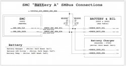
Specifically I am trying to locate the pair of pull-up resistors on the battery I2C bus to G3Hot. Schematic says they are 1K but when I measure the boards I get 10K so schematic might be in error.

Thanks
 

Attachments

  • SMC_BATT_I2C.jpeg
    SMC_BATT_I2C.jpeg
    143.9 KB · Views: 436
Register on MacRumors! This sidebar will go away, and you'll see fewer ads.