Become a MacRumors Supporter for $50/year with no ads, ability to filter front page stories, and private forums.

Techkat

macrumors member
Jan 23, 2013
33
0
Paso Robles, California
Input to the LT3470 is OK but notice the bias/feedback input on pin1 is in mv range. I think your U6990 is probably damaged. Your posted schematic seemed odd as the junction of R6995/R6996 should show a line connecting it to U6990-1. This junction (aka U6990-1) should be around 1.25v.

This board is definitely repairable. That IC is probably only cost a few dollars. How did your hubby connect the 3.42v line called PP3V42_G3H_BATT to the BIL connector pins 1/2/3? Have check to make sure this 3 lines are not shorted to ground or other pins in the connector.

thanks for the input. I dont know the schematic I bought off a site. as far as where he connected it. Well you said to restore the 3.4v to pins 1,2 and 4 i believe so his WIFE told him to connect to pin1 of C6951. But after reading what you said earlier I could of been wrong?????

----------

my readings for D6905 is very similar to Techkats except for the pulsing but I don't get ANY reading for pin 5 :confused: could this be a bad diode?

No problem TechKat, hell of a learning curve lol

Boy are you stating the obvious. LOL
 

cmdrdata

macrumors 6502
Jun 10, 2011
377
2
Dallas, Texas, USA
thanks for the input. I dont know the schematic I bought off a site. as far as where he connected it. Well you said to restore the 3.4v to pins 1,2 and 4 i believe so his WIFE told him to connect to pin1 of C6951. But after reading what you said earlier I could of been wrong???

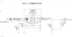
Here's what my schematic for the BIL connector shows. To me it looked like 1/2/3 are connected directly to the G3HOT power supply, i.e., PP3V42_G3H_BATT which is the same as PP3V42_G3H (see page 7D1). And yes, C6951-1 is the correct one, but perhaps he connected it to C6951-2 which is ground, and thus it would drag G3HOT to 0v? Temporarily remove his connection and see if G3HOT bounced back up.

If I had said pin4, I apologize because that is wrong. Pin 4 is SMBUS_BATT_SDA which would measure 3.4v if G3HOT is good because it is being pulled up via a resistor to that level.

PS: In your post #1263, you showed pin4 as G3HOT and that disagreed with the schematic I posted here. I wonder if we are looking at TWO DIFFERENT wiring of BIL connectors?
 

Attachments

  • Screen Shot 2013-02-04 at 5.30.28 PM.png
    Screen Shot 2013-02-04 at 5.30.28 PM.png
    60.8 KB · Views: 323

Techkat

macrumors member
Jan 23, 2013
33
0
Paso Robles, California
Here's what my schematic for the BIL connector shows. To me it looked like 1/2/3 are connected directly to the G3HOT power supply, i.e., PP3V42_G3H_BATT which is the same as PP3V42_G3H (see page 7D1). And yes, C6951-1 is the correct one, but perhaps he connected it to C6951-2 which is ground, and thus it would drag G3HOT to 0v? Temporarily remove his connection and see if G3HOT bounced back up.

If I had said pin4, I apologize because that is wrong. Pin 4 is SMBUS_BATT_SDA which would measure 3.4v if G3HOT is good because it is being pulled up via a resistor to that level.

PS: In your post #1263, you showed pin4 as G3HOT and that disagreed with the schematic I posted here. I wonder if we are looking at TWO DIFFERENT wiring of BIL connectors?

HI CMR, its not you who said pin 4 its me i was going by the boardview file I have. I am going to send it to you so you can view. I would post if for everyone but now I am curious whether its correct. its for a 2009 2.53 15" how do I send it to you.

----------

Here's what my schematic for the BIL connector shows. To me it looked like 1/2/3 are connected directly to the G3HOT power supply, i.e., PP3V42_G3H_BATT which is the same as PP3V42_G3H (see page 7D1). And yes, C6951-1 is the correct one, but perhaps he connected it to C6951-2 which is ground, and thus it would drag G3HOT to 0v? Temporarily remove his connection and see if G3HOT bounced back up.

If I had said pin4, I apologize because that is wrong. Pin 4 is SMBUS_BATT_SDA which would measure 3.4v if G3HOT is good because it is being pulled up via a resistor to that level.

PS: In your post #1263, you showed pin4 as G3HOT and that disagreed with the schematic I posted here. I wonder if we are looking at TWO DIFFERENT wiring of BIL connectors?


P.s. Its a 820-2933 logic board and thats what I bought.
 

Attachments

  • LB#820-2533 bil.pdf
    124.8 KB · Views: 622
  • 820--2533 bv bil.pdf
    174.2 KB · Views: 352
Last edited:

Techkat

macrumors member
Jan 23, 2013
33
0
Paso Robles, California
Here's what my schematic for the BIL connector shows. To me it looked like 1/2/3 are connected directly to the G3HOT power supply, i.e., PP3V42_G3H_BATT which is the same as PP3V42_G3H (see page 7D1). And yes, C6951-1 is the correct one, but perhaps he connected it to C6951-2 which is ground, and thus it would drag G3HOT to 0v? Temporarily remove his connection and see if G3HOT bounced back up.

If I had said pin4, I apologize because that is wrong. Pin 4 is SMBUS_BATT_SDA which would measure 3.4v if G3HOT is good because it is being pulled up via a resistor to that level.

PS: In your post #1263, you showed pin4 as G3HOT and that disagreed with the schematic I posted here. I wonder if we are looking at TWO DIFFERENT wiring of BIL connectors?

Ok CMR I posted the schematic page with the bil and the boardview with the bil and cap we are talking about. thank you again.
 

ace2000

macrumors newbie
Feb 3, 2013
23
0
Hi i knocked up a diagram of my test results on the D6905, would it be possible for one of you guys too have a quick look ;)
D6905Diag.png


could the 0 volt be why I have no G3HOT ?
 
Last edited:

Techkat

macrumors member
Jan 23, 2013
33
0
Paso Robles, California
Hi i knocked up a diagram of my test results on the D6905, would it be possible for one of you guys too have a quick look ;) Image

could the 0 volt be why I have no G3HOT ?

Hey ace, They will answer you, they are so good about that, but it definately looks like it to me. but again I am the who just messed up the one she is working on.
 

cmdrdata

macrumors 6502
Jun 10, 2011
377
2
Dallas, Texas, USA
HI CMR, its not you who said pin 4 its me i was going by the boardview file I have. I am going to send it to you so you can view. I would post if for everyone but now I am curious whether its correct. its for a 2009 2.53 15" how do I send it to you.
P.s. Its a 820-2933 logic board and thats what I bought.

Techkat, in the above sentence you said 820-2933, but the pdf files you posted shows 820-2533, so there is a discrepancy already. Secondly, when I posted my BIL schematic, it was for a Mid2009 MBP13U (MBP 13" unibody), so I think You and I need to be on the same page to be able to communicate correctly. Unfortunately, I do not have schematic and Board View for your specific Mac, thus the reason I used what I have to explain my point. Thirdly, it is clear to me now that we have to be very careful when talking pinouts etc, because based on what you just posted, APPLE did change the pinouts of where the LID, SDA/SCL, and G3HOT lines go to for different MBPs and screen sizes, so be careful with that. I think all the explanation I have given to you and others is correct from a FUNCTIONAL standpoint, BUT it needs to be modulated to a specific logic board to be precise for pin designation etc.
PS: On the boardview pic posted, it was not labeled, but is C6951-1 the closest to U6990 or the top part of it?
 

cmdrdata

macrumors 6502
Jun 10, 2011
377
2
Dallas, Texas, USA
Hi i knocked up a diagram of my test results on the D6905, would it be possible for one of you guys too have a quick look ;) Image

could the 0 volt be why I have no G3HOT ?

This drawing tells me that D6905 is working correctly. The 2 pins on the left showing 16v or so and they have the same voltage is because they are tied together (the common cathode). The top right is 0v because your battery is not outputting any voltage. If it were, you'd see about 12v there. The bottom right is the voltage from the magsafe. The slight difference in left and right voltages is the voltage drop across the diode. So this chip is doing what it is supposed to, nothing wrong with it.

Next you need to look at pin 1 of U6990 (LT3470 chip). It should have 1.25v. This is the feedback reference voltage that the chip monitors to maintain 3.42v output. Notice that
G3HOT=3.42v = 1.25v x (R6995 + R6996) / R6996. So by the chip keeping pin1 at 1.25v, the output on pin4 (a pulsed square wave that is then smoothed/filtered by L6995 and C6999 becomes effectively DC voltage of 3.42v.
 

Techkat

macrumors member
Jan 23, 2013
33
0
Paso Robles, California
Techkat, in the above sentence you said 820-2933, but the pdf files you posted shows 820-2533, so there is a discrepancy already. Secondly, when I posted my BIL schematic, it was for a Mid2009 MBP13U (MBP 13" unibody), so I think You and I need to be on the same page to be able to communicate correctly. Unfortunately, I do not have schematic and Board View for your specific Mac, thus the reason I used what I have to explain my point. Thirdly, it is clear to me now that we have to be very careful when talking pinouts etc, because based on what you just posted, APPLE did change the pinouts of where the LID, SDA/SCL, and G3HOT lines go to for different MBPs and screen sizes, so be careful with that. I think all the explanation I have given to you and others is correct from a FUNCTIONAL standpoint, BUT it needs to be modulated to a specific logic board to be precise for pin designation etc.
PS: On the boardview pic posted, it was not labeled, but is C6951-1 the closest to U6990 or the top part of it?

Sorry i Meant 2533 and yes its the closet if you zoom in on the pdf sent I made sure that the pinout was labeled. No I believe you told me right and what you said was functional I am saying if there is any mixup it was me. I will post the files for download but will pull them if you tell me they are wrong . Thank you so much

Schematic and Boardview File
 

cmdrdata

macrumors 6502
Jun 10, 2011
377
2
Dallas, Texas, USA
Sorry i Meant 2533 and yes its the closet if you zoom in on the pdf sent I made sure that the pinout was labeled. No I believe you told me right and what you said was functional I am saying if there is any mixup it was me. I will post the files for download but will pull them if you tell me they are wrong . Thank you so much

Schematic and Boardview File

Thanks. I got it downloaded. Now I see that for different MBPs, the BILs are wired differently. Darn Apple Computer. So for you techkat, 1/2/4 should be connected to PP342_G3H. With power off, check to see if 1/2/4 on the BIL is shorted to ground. If it is, disconnect the wire your hubby put in and check again. These pins should not have a 0 ohm or low resistance to ground.

If they checked out ok, with the wire still disconnected check C6951-1 to see if that is shorted to ground. If it is, then my guess is U6990 is toast.
 

ace2000

macrumors newbie
Feb 3, 2013
23
0
Thankyou cmdrdata, just tested U6990 and I only have 0.13v:eek: at pin1, what does this tell you ?.. thanks for helping... Justin.
 

cmdrdata

macrumors 6502
Jun 10, 2011
377
2
Dallas, Texas, USA
Thankyou cmdrdata, just tested U6990 and I only have 0.13v:eek: at pin1, what does this tell you ?.. thanks for helping... Justin.

Check the other pins:
6/8 should be the same as 4/5 of the D6950
2/4 should be around 3.4v if G3HOT is working as it should

with no power applied:
pin2 of L6995 should not be low resistance to ground.
L6995 should measure almost 0 Ohm with your ohm meter
R6995 and R6996 should be whatever your schematic tells you.
None of the capacitors around it should be shorted
If these all checked out, then .... order U6990 and replace?
 

Techkat

macrumors member
Jan 23, 2013
33
0
Paso Robles, California
Thanks. I got it downloaded. Now I see that for different MBPs, the BILs are wired differently. Darn Apple Computer. So for you techkat, 1/2/4 should be connected to PP342_G3H. With power off, check to see if 1/2/4 on the BIL is shorted to ground. If it is, disconnect the wire your hubby put in and check again. These pins should not have a 0 ohm or low resistance to ground.

If they checked out ok, with the wire still disconnected check C6951-1 to see if that is shorted to ground. If it is, then my guess is U6990 is toast.

OK CMD,

You are an absolute genius. It was shorting out to ground pins 1,2,4. if you look back at my post 1253 the picture of the connector J6955 was messed up so it was hard for him to do it. Thats why he was mad after I tried to connect bil thinking it would make it sleep when lid was closed.

I can tell you for sure without a doubt that it was not that way before I tried to connect it, I say stupid blonde girl, but really I know a little more than that. I checked double checked it all with meter for continuity to right places, after he finished soldering as I always do, then when I plugged in the magsafe I checked with meter before I turned it on. It ran for a good 15 to 20 min while I was trying to see if it would go to sleep, no so thats when I got that bright idea of turning off and plugging in connector.

I was actually going to major in electronics technology, it has always interested me very much. I started first semester (lots of math, very little hands on that semester, but my boss where I just got a job talked me out of it because he wanted me to travel for him and he had a large area to cover in San Fernando Valley(onsite Computer Repair). So I never finished. but i have a very basic understanding extremely basic. I checked into it again at the local jr college here where I live now. I am really considering getting back into it. Anyhow nuff of me. I now have 3.35 volts in all the places I used to have 3.4v. Green light is on magsafe. Do you think I should try to jump start.
 

ace2000

macrumors newbie
Feb 3, 2013
23
0
Check the other pins:
6/8 should be the same as 4/5 of the D6950
2/4 should be around 3.4v if G3HOT is working as it should

did you mean D6905? I am sure you did so I will test this next (only because D6950 looks like its got 3 pins lol)
 

ace2000

macrumors newbie
Feb 3, 2013
23
0
UPDATE:

right as I was testing U6990 I noticed corrosion on the lower pins

1-1.png


So I whipped it off and cleaned it up...

3.png


Doesn't look to good :( Pin 6 is missing and its the same on the board..

4.png


Is this Game over? or can I replace U6990 (if so where could i buy this?) and maybe put a jump lead to pin 6, or am I just wasting my time... Thanks for all the help Justin..
 

cmdrdata

macrumors 6502
Jun 10, 2011
377
2
Dallas, Texas, USA
UPDATE:

right as I was testing U6990 I noticed corrosion on the lower pins

Image

So I whipped it off and cleaned it up...

Image

Doesn't look to good :( Pin 6 is missing and its the same on the board..

Image

Is this Game over? or can I replace U6990 (if so where could i buy this?) and maybe put a jump lead to pin 6, or am I just wasting my time... Thanks for all the help Justin..

The game is not over. I think LT3370 is easily available through various vendors in the USA. Google it and make sure it has the same IC package. Once you install it, restore the pin 6 connectivity using point-to-point "blue wire". In my days (early 70's) blue wire is plentiful. This is a 30ga. single strand wire, typically used for breadboarding using wire-wrap boards. Tack one end to pin 6 of the chip and the other end to wherever it should have been connected to, then secure the wire down flat with Kapton tape. PLEASE NOTE that like the BIL connector I discussed with Techkat, LT3470 comes in different flavors pin out wise for older vs newer MBPs, so you have to use the correct replacement part. Oh, perhaps you should flatten one end of the 30ga blue wire and tack onto pin 6 of the chip before reflowing the chip onto the board. I just noticed that this chip has pads on the bottom instead of fingers.

PS: yes, in my previous post I meant D6905
 
Last edited:

Musicsoul78

macrumors regular
Aug 24, 2012
111
0
UK ESSEX
Yes It did work, the temp grounding.

I am not good at soldering, but my husband is. He used to work at Northrop years ago, Teenager soldering on boards. They were a whole different species then. Anyways what I am saying is he does not work on computers so He doesn't like to solder but I'm lucky in the fact that he does it for me.

When I showed him what you were asking for he did it, it still didn't change the going to sleep, so there was probably still something I didnt hit on, but it ran. Then dumb blonde girl steps in and connects the bil cable and now no 3.4v, needless to say husband not happy with me.

So are you saying that the whole board is now a parts board. I have been kicking myself in but all week. I read the post before with Ace2000 so I started checking those things and here is what I have if it helps.

Thank you for your help

Oh and you are not on a podium, You are Just helping people and believe me we take what you say as helping in no other way is it taken by me. Thanks again.

i agree with techkat

never a truer word spoken...

tower of knowledge

ty commander
 

ace2000

macrumors newbie
Feb 3, 2013
23
0
Last edited:

cmdrdata

macrumors 6502
Jun 10, 2011
377
2
Dallas, Texas, USA
Ah great news cmdrdata :D, I am in the UK so we have RS components and Farnell,

I have found these they don't have the A on the end but do you think they will work?

http://uk.rs-online.com/web/p/buck-converters/0423567/

http://uk.rs-online.com/web/p/dc-dc-converters/7618709/

thanks for your help Justin...

Don't know the difference between non-A and A designated devices. If the package description and pin out matches, then you're good to go. The vendor spec you shown has leads, but the posted picture in previous forum post did not .....?
 

ace2000

macrumors newbie
Feb 3, 2013
23
0
Cheers cmdrdata, maybe with the resistors going (see last edit in last post) it might be getting too much :( but can you imagine if i did get it working :), it just seems that I am getting close .....

also no reading on R6905 47 ohm resistor..

also looks like pin 6 is the feed so i could just take it from pin 4 or 5 of D6905 where it would have originated from does this sound ok?, also have some enamel wire knocking about really fine stuff that should do the trick.... Justin.
 
Last edited:

Techkat

macrumors member
Jan 23, 2013
33
0
Paso Robles, California
Thank you cmdrdata!!!

Thank you CMDRDATA, I know I am probably speaking for everyone when I say to you THANK YOU. We appreciate your knowledge and your willingness to help us. It shows the integrity of the person you are. You said you recently retired, well I'm pretty sure that company is sorely missing you. Their loss is our gain. LOL. I wanted to tell you I got it going I did jump it and it started. I dont have sleep mode but I can manually do that. I guess when I pushed in bil cable I pushed down wire so it was touching the ground. I was ready to throw board away. If there is any thing you need please ask me. like boardview files, you also Music schematics, etc. I will get them up for you. If I have them they are yours. You probably don't need them like most of us, but their yours for the asking guys. :)
 

cmdrdata

macrumors 6502
Jun 10, 2011
377
2
Dallas, Texas, USA

I checked out the specs, and it seemed to me the package you need is type DDB8. See attached.

If you do not measure ~47 Ohm for R6905, you will need that restored too, otherwise you'll not be able to provide Vin to U6990 from the magsafe. The battery source does not have a limiting resistor. And yes, pin 4/5 of D6905 is where the U6990 got its input. Caution: note that pin9 (center pad of U6990) according to the spec must also be grounded, so when you install this new part make sure the center pad also have flux and solder.
 

Attachments

  • Screen Shot 2013-02-05 at 2.05.56 PM.png
    Screen Shot 2013-02-05 at 2.05.56 PM.png
    49.9 KB · Views: 261

ace2000

macrumors newbie
Feb 3, 2013
23
0
thanks for that cmdrdata i will replace the 47 ohm resistor and the both r6995 and R6996 as I am getting no reading there either, I will check the rest of this circuit and order everything i need,

G3HOTsupply.png


just to add I feel the exact same as Techkat you are a top bloke we very much appreciate it, I know I myself would be totally lost with all this without your guidance but I have read and re read all the thread and I must say I am enjoying all this detective work, I just wish I would have gone to college for it when i was younger, they want a £8995 to enrol you on a course now :( but I am finding it really interesting.

again thank you very much.... ;)
 

Techkat

macrumors member
Jan 23, 2013
33
0
Paso Robles, California
2009 13" 2.53

I have a 13" 2009 just like the schematic and board view I posted for Ace2000 yesterday I am kind of stumped because I have all the right voltages it seems in all the right places including the 3.4 on the jumper pad. but I cant start. I have tried in and out of body. I was thinking it had something to do with power button or keyboard connector cable so when i took out keyboard cable, and tried to jump it from pads or 5th pin and ground still nothing . It has green light, it charges. etc. If anyone has any ideas to try I'm open for suggestions.
 
Register on MacRumors! This sidebar will go away, and you'll see fewer ads.