Become a MacRumors Supporter for $50/year with no ads, ability to filter front page stories, and private forums.

unknown11

macrumors newbie
Jan 29, 2013
9
0
anytime and goodluck

if you fix let us know what part of the board that your specific case was effected. providing knowledge for others is key

thanks

----------


you have probably already done this but have you checked the 2 6a fuses.

2 big white fuses one on each side of your 2011 model

1 by the battery

and 1 by the dc jack underside of logic board


sometimes its the the simple things!

Both fuses measure the same voltage as what the battery and magsafe are giving them, and I can measure this same voltage downstream from the fuses. So they both seem to be conducting the low voltages properly. Is there anyway they could cause the battery and/or magsafe to act they way they are in case?
 

Musicsoul78

macrumors regular
Aug 24, 2012
111
0
UK ESSEX
Both fuses measure the same voltage as what the battery and magsafe are giving them, and I can measure this same voltage downstream from the fuses. So they both seem to be conducting the low voltages properly. Is there anyway they could cause the battery and/or magsafe to act they way they are in case?

i thought you were not receiving a voltage... they way i read it the board was completely dead.

when those fuses on any of my boards die the power flow changes dramatically either way.

have submitted any pics of your board yet??


btw do you know the pin out v's of a 2011 mbp 13" wled driver??
 

unknown11

macrumors newbie
Jan 29, 2013
9
0
i thought you were not receiving a voltage... they way i read it the board was completely dead.

when those fuses on any of my boards die the power flow changes dramatically either way.

have submitted any pics of your board yet??


btw do you know the pin out v's of a 2011 mbp 13" wled driver??

I do have low voltage. I have what you might call "leakage" coming from the magsafe giving pins 2&4 on DCIN board, pins 1&2 at DCIN jack, and the fuse near the DCIN jack ~0.19 volts. Same is true for areas on the board where PPDCIN_G3H inputs.
I get this same sort of "leakage" coming from the battery as well, giving battery pins 7-9 and pin 5 of Q7055 ~0.20 volts, but pins 1-3 of Q7055 and the battery fuse are ~0.12 volts. The ares on the board where PPBUS_G3H inputs are also ~0.12 volts.
The whole rundown is in my previous post( post #1268) but long story short I traced the PPDCIN_G3H and PPBUS_G3H to the common cathode diode D6990. I measured the 0.19 volts of PPDCIN and 0.12 volts of PPBUS at there respective anodes but got nothing coming out the cathode, which is where U6990 gets the signal that tells it to enable G3HOT (PP3V42_G3H) on this model board, 820-2936. You can find this on pg.63 of the schematic I attached to post #1268.
Now I thought that because G3HOT isn't being enabled that there would be NO signal back to the magsafe through pin 5 of DCIN jack/ pin 3 of the magsafe to tell it to release the full ~16.5 volts or so. Therefore, causing the voltage to drop off as is seen on my board. Same goes for the battery. How could the battery be enabled by the SMC if there is no 3.425 volts from PP3V42_G3H to power the SMC? It seems as if the battery, and I suppose the magsafe as well, goes into shutdown mode because this cycle can't be complete.
It seems like a rare case, but I think the reason why BOTH the battery and magsafe, which are known functional ones, aren't giving the board there full power is because of this D6990 diode. But I really don't know how to confirm this theory, and I don't want to start soldering off parts on a whim and risk permanently damaging the board. So now I'm here on this forum to see what you all think.
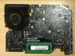
I apologize for rambling on again. I'm sorry Musicsoul but I'm not familiar with the wled driver. Hopefully the schematic I posted can help you get info on it. Two whole views of my board are attached below. See post #1268 for a close up of D6990.
 

Attachments

  • image.jpeg
    image.jpeg
    892 KB · Views: 790
  • photo (3).JPG
    photo (3).JPG
    2.7 MB · Views: 787

Musicsoul78

macrumors regular
Aug 24, 2012
111
0
UK ESSEX
I HAVE MBP 13 2010

water damage, cleaned it booted ..

screen had no backlight - replaced fuse

backlight worked but screen was flickering then fuse blew again

so i replaced a again then same thing happened.

after the 3rd time it blew i noticed the big 6a fuse, white was not right value so i replaced.

all fuses are now testing perfect but now is will not power on.

ghot
left pad is 3.40
right pad is not grounded so it will not boot.
and will not boot at keyboard connectors either.

magsafe is good green then Orange light
dc in is all so good


what has happened.??? i checked the board for shorts non present

what could cause the right pad not to complete the circuit

many thanks guys

----------

I do have low voltage. I have what you might call "leakage" coming from the magsafe giving pins 2&4 on DCIN board, pins 1&2 at DCIN jack, and the fuse near the DCIN jack ~0.19 volts. Same is true for areas on the board where PPDCIN_G3H inputs.
I get this same sort of "leakage" coming from the battery as well, giving battery pins 7-9 and pin 5 of Q7055 ~0.20 volts, but pins 1-3 of Q7055 and the battery fuse are ~0.12 volts. The ares on the board where PPBUS_G3H inputs are also ~0.12 volts.
The whole rundown is in my previous post( post #1268) but long story short I traced the PPDCIN_G3H and PPBUS_G3H to the common cathode diode D6990. I measured the 0.19 volts of PPDCIN and 0.12 volts of PPBUS at there respective anodes but got nothing coming out the cathode, which is where U6990 gets the signal that tells it to enable G3HOT (PP3V42_G3H) on this model board, 820-2936. You can find this on pg.63 of the schematic I attached to post #1268.
Now I thought that because G3HOT isn't being enabled that there would be NO signal back to the magsafe through pin 5 of DCIN jack/ pin 3 of the magsafe to tell it to release the full ~16.5 volts or so. Therefore, causing the voltage to drop off as is seen on my board. Same goes for the battery. How could the battery be enabled by the SMC if there is no 3.425 volts from PP3V42_G3H to power the SMC? It seems as if the battery, and I suppose the magsafe as well, goes into shutdown mode because this cycle can't be complete.
It seems like a rare case, but I think the reason why BOTH the battery and magsafe, which are known functional ones, aren't giving the board there full power is because of this D6990 diode. But I really don't know how to confirm this theory, and I don't want to start soldering off parts on a whim and risk permanently damaging the board. So now I'm here on this forum to see what you all think.
I apologize for rambling on again. I'm sorry Musicsoul but I'm not familiar with the wled driver. Hopefully the schematic I posted can help you get info on it. Two whole views of my board are attached below. See post #1268 for a close up of D6990.

what is the part number for this d6990 diode??

i will test it on mine first if you want?
 

unknown11

macrumors newbie
Jan 29, 2013
9
0
what is the part number for this d6990 diode??

i will test it on mine first if you want?

D6990:
Part # = BAT30CWFILM
Top Mark = C30
Package = Sot-323

Here's the data sheet for the company that makes it:
http://www.st.com/internet/com/TECHNICAL_RESOURCES/TECHNICAL_LITERATURE/DATASHEET/CD00126118.pdf

I did some further testing with my multimeter set to the diode function switch. With red lead on the anode and black on the cathode I got a forward voltage of 0.25 volts for both anodes, which matches the values I got for the good board I have. But when I reverse the leads and place the black lead on anode #1 (the PPBUS_G3H pin in) I get 0.52 volts!!! According to what a normal/functional diode test should give, I should get NO foward voltage in the reverse direction. Right? I confirmed it with my good board and got the zero voltage there.
I also tested for forward voltage between the two anodes. With black lead on anode #1 and red on anode #2, I got 0.86 volts!!! Zero with the my good board.
Does this seem like more evidence to support my theory that this diode could be the cause for my power issues?
Musicsoul, if you could give yours a test and let me know what you think that would be great.
 

Musicsoul78

macrumors regular
Aug 24, 2012
111
0
UK ESSEX
D6990:
Part # = BAT30CWFILM
Top Mark = C30
Package = Sot-323

Here's the data sheet for the company that makes it:
http://www.st.com/internet/com/TECHNICAL_RESOURCES/TECHNICAL_LITERATURE/DATASHEET/CD00126118.pdf

I did some further testing with my multimeter set to the diode function switch. With red lead on the anode and black on the cathode I got a forward voltage of 0.25 volts for both anodes, which matches the values I got for the good board I have. But when I reverse the leads and place the black lead on anode #1 (the PPBUS_G3H pin in) I get 0.52 volts!!! According to what a normal/functional diode test should give, I should get NO foward voltage in
the reverse direction. Right? I confirmed it with my good board and got the zero voltage there.
I also tested for forward voltage between the two anodes. With black lead on anode #1 and red on anode #2, I got 0.86 volts!!! Zero with the my good board.
Does this seem like more evidence to support my theory that this diode could be the cause for my power issues?
Musicsoul, if you could give yours a test and let me know what you think that would be great.

reading taken when removed just after magsafe removal

anode 1# to cathode 0.25
reversed -0.25

anode1# to anode2# 0.17
reversed -0.17

one more test anode 2# cathode -0.2
reversed 0.2

i will remove component and try
power later tonight to power board
 

unknown11

macrumors newbie
Jan 29, 2013
9
0
reading taken when removed just after magsafe removal

anode 1# to cathode 0.25
reversed -0.25

anode1# to anode2# 0.17
reversed -0.17

one more test anode 2# cathode -0.2
reversed 0.2

i will remove component and try
power later tonight to power board

Weird. Well let me know how it goes.
 

Musicsoul78

macrumors regular
Aug 24, 2012
111
0
UK ESSEX
Weird. Well let me know how it goes.

removed component = no power

i dont know how this helps

but i hope it does in some way

i think CMRDATA is right just check the u6900 or equivalent into giving your adapter the release on sense line pin5.

i really wish i could have a quick fix for ya buddy. sorry
 
Last edited:

unknown11

macrumors newbie
Jan 29, 2013
9
0
removed component = no power

i dont know how this helps

but i hope it does in some way


Interesting. Did you happen to check voltages around the board? For instance at the fuses near the DCIN and battery. I'm wondering if, with that component removed, you got those same low low voltages I'm getting. I think that would be the nail in the coffin I'm looking for before I attempt to replace this component myself or pay someone else to do it.
 

Musicsoul78

macrumors regular
Aug 24, 2012
111
0
UK ESSEX
Replace the component yourself as it took me 2mins to remove using flux and standard soldering iron .
Part is also very cheap

Ps did not get any voltages what so ever.
It is one of the key components
 

ace2000

macrumors newbie
Feb 3, 2013
23
0
Hi, what can I say this is a fantastic thread i've learned loads,
I've read up to page 25 about 600 odd posts but because of the learning curve I have to re read so it takes ages, So I thought i would post my problem while I am still reading otherwise it will never get done lol,

Here goes....

I have a MBP 13 mid 2009 A1278 same as the thread starter i think.. I don't know the history of the machine all he said was it doesn't power up,
So I opened her up board looks untouched no visible damage screws untouched but I removed logic board and cleaned with 99% IPA anyway, let dry over night reinstalled and got no power totally dead no battery light nothing,
So I tested both fuses the one on the CPU side gets 16.5 ish Volts the one down near the battery gets 0 volts and G3HOT gets 0 volts, oh and the magsafe flashes dim amber,
I think the problem may be the battery I am getting no voltage when i test the battery (am I testing this right 1st 3 pins ground last 3 pins Vcc) So if the battery has died i wont be getting the 3.42v to the G3HOT and the SMC will have no power,
The thing thats confusing me though is people can run their boards just on the magsafe, oh and i've tries SMC reset, bridging G3HOT pads with and without grounding the keyboard but still not a hint of life,
So really my questions are can a bad battery cause this? Do I need to be measuring anything else?
Thanks for your time.... Justin.
 

ace2000

macrumors newbie
Feb 3, 2013
23
0
microdcin.png
also I have just tested the DC IN board pic (attached) and shorted to pins together :eek: anyhow this is the result I get, i think there should be some voltage on the centre pin and dont have any:confused:
 
Last edited:

cmdrdata

macrumors 6502
Jun 10, 2011
377
2
Dallas, Texas, USA
Imagealso I have just tested the DC IN board pic (attached) and shorted to pins together :eek: anyhow this is the result I get, i think there should be some voltage on the centre pin and dont have any:confused:

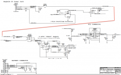
Justin, as shown in the attached drawing, the magsafe power if present (it is definitely on with you reading 16.5v) should go directly to the G3HOT circuitry. Therefore if you do not have G3HOT with just magsafe, trace it where it breaks down i.e., this power should go through DCIN connector pins 1/2, fuse F6905, resistor R6905, diode pair D6905 pin 1 and ends up into VIN(put) of U6990. This is the regulator chip that generates a "hot" (meaning always on) 3.42v aka G3HOT. If this voltage is being generated correctly, it then provides power the SMC to do its power on sequencing when power turn on signal is given. It will also allows the SMC to communicate with the magsafe and turn the LED to the appropriate color of green or orange.
 

Attachments

  • Screen Shot 2013-02-03 at 7.21.01 PM.png
    Screen Shot 2013-02-03 at 7.21.01 PM.png
    134.4 KB · Views: 1,463

ace2000

macrumors newbie
Feb 3, 2013
23
0
Thanks Cmdrdata, the problem I am having at the minute is locating the components you refer too :confused: It seems like folk are using board viewer files to do this, does anyone know where i could get one for a mid 2009 MBP 13... Thanks Justin..
 

ace2000

macrumors newbie
Feb 3, 2013
23
0
Just finished reading all 52 pages lol, but still struggling where to find these components mentioned :( if someone could link me to a place I could buy the mid 2009 MBP 13 2.53ghz board view file, I already have schematic from somewhere on this thread... Thanks Justin.:)
 

Techkat

macrumors member
Jan 23, 2013
33
0
Paso Robles, California
What would I do now.

anytime and goodluck

if you fix let us know what part of the board that your specific case was effected. providing knowledge for others is key

thanks


Hi guys,

I didn't get a chance to work on the problem til this weekend. I tried the magnet trick to no avail. I tried shorting it to ground like CMRDATA suggested and it went to sleep immediately. So I asked my husband ( poor guy, I always have him do the soldering) to assist. He helped run the 3.4v to the pins suggested and made sure that smc_lid was connected through to pin 8. I tried again and it was the same (In other words everything worked great but did not go to sleep) but I did not connect the bil cable in. Then I thought I would try the new one I just purchased and I lost the entire line of 3.4v. I HAVE NO CLUE WHERE TO GO NOW. If you have any suggestions I would much appreciate it. DUMB BLONDE GIRL STRIKES AGAIN.

----------

Just finished reading all 52 pages lol, but still struggling where to find these components mentioned :( if someone could link me to a place I could buy the mid 2009 MBP 13 2.53ghz board view file, I already have schematic from somewhere on this thread... Thanks Justin.:)


Hi Justin I have what you need I have the schematic and the board view files which so greatly helps you locate the part in question. I am new to the forum stuff so I am not sure how to get it to you but If I can get your email I can send it to you.

Kathy
 
Last edited:

cmdrdata

macrumors 6502
Jun 10, 2011
377
2
Dallas, Texas, USA
I didn't get a chance to work on the problem til this weekend. I tried the magnet trick to no avail. I tried shorting it to ground like CMRDATA suggested and it went to sleep immediately. So I asked my husband ( poor guy, I always have him do the soldering) to assist. He helped run the 3.4v to the pins suggested and made sure that smc_lid was connected through to pin 8. I tried again and it was the same (In other words everything worked great but did not go to sleep) but I did not connect the bil cable in. Then I thought I would try the new one I just purchased and I lost the entire line of 3.4v. I HAVE NO CLUE WHERE TO GO NOW. If you have any suggestions I would much appreciate it. DUMB BLONDE GIRL STRIKES AGAIN.
Kathy

So, it seemed my theory work as far as forcing to sleep is concerned, i.e., logic zero on that pin causes it to sleep. As your for the new 3.4v problem, it would be a mistake to wire 3.4v from G3HOT supply directly to that pin unless that pin really need 3.4v voltage source instead of signal line being pulled up to 3.4v via a resistor. I think a lot of people here think that shorting G3HOT to GND is physically doing so. This is dangerous because it will cause unintended problem/failure. This is like shorting a 3.4v power supply to ground. I'd guess your 3.4v G3HOT supply is now possibly toast? In the parlay of logic circuit, many signal and sensor lines are connected to, say G3HOT via individual resistors, typically called a "pull-up" resistors. So, if you measure the other end of that resistor with a voltmeter, you will indeed see 3.4v or thereabout. This end can be safely grounded very briefly to pulse the line to ground, and thus sends a signal to the receiving end such as the SMC. So, just because one measures 3.4v it is NOT THE SAME as the 3.4v source power supply voltage. I'll get off the podium now.
 
Last edited:

Techkat

macrumors member
Jan 23, 2013
33
0
Paso Robles, California
So, it seemed my theory work as far as forcing to sleep is concerned, i.e., logic zero on that pin causes it to sleep. As your for the new 3.4v problem, it would be a mistake to wire 3.4v from G3HOT supply directly to that pin unless that pin really need 3.4v voltage source instead of signal line being pulled up to 3.4v via a resistor. I think a lot of people here think that shorting G3HOT to GND is physically doing so. This is dangerous because it will cause unintended problem/failure. This is like shorting a 3.4v power supply to ground. I'd guess your 3.4v G3HOT supply is now possibly toast? In the parlay of logic circuit, many signal and sensor lines are connected to, say G3HOT via individual resistors, typically called a "pull-up" resistors. So, if you measure the other end of that resistor with a voltmeter, you will indeed see 3.4v or thereabout. This end can be safely grounded very briefly to pulse the line to ground, and thus sends a signal to the receiving end such as the SMC. So, just because one measures 3.4v it is NOT THE SAME as the 3.4v source power supply voltage. I'll get off the podium now.

Yes It did work, the temp grounding.

I am not good at soldering, but my husband is. He used to work at Northrop years ago, Teenager soldering on boards. They were a whole different species then. Anyways what I am saying is he does not work on computers so He doesn't like to solder but I'm lucky in the fact that he does it for me.

When I showed him what you were asking for he did it, it still didn't change the going to sleep, so there was probably still something I didnt hit on, but it ran. Then dumb blonde girl steps in and connects the bil cable and now no 3.4v, needless to say husband not happy with me.

So are you saying that the whole board is now a parts board. I have been kicking myself in but all week. I read the post before with Ace2000 so I started checking those things and here is what I have if it helps.

Thank you for your help

Oh and you are not on a podium, You are Just helping people and believe me we take what you say as helping in no other way is it taken by me. Thanks again.
 

Attachments

  • LB#820-2533 3.jpg
    LB#820-2533 3.jpg
    113.4 KB · Views: 1,447
Last edited:

ace2000

macrumors newbie
Feb 3, 2013
23
0
just a quick one while I am still testing ;)

my R6905 is pulsing between 14.00v and 14.50v on one side and 16.80v and 17.15v on the other side (or near enough its difficult to say as it pulses to quick through the numbers lol)

tried reading resistance but no reading,

do you think this component could be bad?

thanks very very much Justin.. ;)

----------

thats great Kathy just what I need :D are all those readings off a good board? seems I am not that far off on the R6905 apart from the pulsing :confused:

But still confused regarding the resistance I went through all the different ohm settings one probe on each end, still very new to this lol
 

Techkat

macrumors member
Jan 23, 2013
33
0
Paso Robles, California
just a quick one while i am still testing ;)

my r6905 is pulsing between 14.00v and 14.50v on one side and 16.80v and 17.15v on the other side (or near enough its difficult to say as it pulses to quick through the numbers lol)

tried reading resistance but no reading,

do you think this component could be bad?

Thanks very very much justin.. ;)

----------

thats great kathy just what i need :d are all those readings off a good board? Seems i am not that far off on the r6905 apart from the pulsing :confused:

But still confused regarding the resistance i went through all the different ohm settings one probe on each end, still very new to this lol

no justin do not go by those readings i am asking just as you are to the forum. The board with those readings, i messed up, it has no 3.4v so after i read what cmr said to you i decided maybe it was a place to start. So i just put them down hoping cmr or someone else can tell me if my board is a parts board or a computer.

Yeah I am just good for research here. when it comes to component level repair. If its documents or board view, If I have it I will share it with anyone here, but I also have just started looking into it and would never consider myself a person to ask. We are lucky though because there are many skilled and knowledgeable people here who are very generous with the knowledge or experiences they have, and we all appreciate them.

The boardview is nice, huh to locate components. Good Luck, Justin
 
Last edited:

cmdrdata

macrumors 6502
Jun 10, 2011
377
2
Dallas, Texas, USA
Yes It did work, the temp grounding.

I am not good at soldering, but my husband is. He used to work at Northrop years ago, Teenager soldering on boards. They were a whole different species then. Anyways what I am saying is he does not work on computers so He doesn't like to solder but I'm lucky in the fact that he does it for me.

When I showed him what you were asking for he did it, it still didn't change the going to sleep, so there was probably still something I didnt hit on, but it ran. Then dumb blonde girl steps in and connects the bil cable and now no 3.4v, needless to say husband not happy with me.

So are you saying that the whole board is now a parts board. I have been kicking myself in but all week. I read the post before with Ace2000 so I started checking those things and here is what I have if it helps.

Thank you for your help

Oh and you are not on a podium, You are Just helping people and believe me we take what you say as helping in no other way is it taken by me. Thanks again.

Input to the LT3470 is OK but notice the bias/feedback input on pin1 is in mv range. I think your U6990 is probably damaged. Your posted schematic seemed odd as the junction of R6995/R6996 should show a line connecting it to U6990-1. This junction (aka U6990-1) should be around 1.25v.

This board is definitely repairable. That IC is probably only cost a few dollars. How did your hubby connect the 3.42v line called PP3V42_G3H_BATT to the BIL connector pins 1/2/3? Have check to make sure this 3 lines are not shorted to ground or other pins in the connector.
 

ace2000

macrumors newbie
Feb 3, 2013
23
0
my readings for D6905 is very similar to Techkats except for the pulsing but I don't get ANY reading for pin 5 :confused: could this be a bad diode?

No problem TechKat, hell of a learning curve lol
 
Register on MacRumors! This sidebar will go away, and you'll see fewer ads.