Become a MacRumors Supporter for $50/year with no ads, ability to filter front page stories, and private forums.

Techkat

macrumors member
Jan 23, 2013
33
0
Paso Robles, California
Macbook Pro 2009 15"

Hi,

I just wanted to let everyone here know that what you are doing is so invaluable you could never put a price on it. I am a computer tech by trade. I have been in the business for 15 years plus. Forums such as these are my best source for different problems that I might run into in the field, and they have helped me fix many a computer and in turn make many a happy customer. I am newer to the Apple world. Although my very first computer was an Macintosh SE, then I graduated to a LC. All my experience in the field has been with PC's. Untill a customer asked me to look at his Macbook Pro. That's it I am totally hooked!! So for the last 6 months when I am not out in the field, I am at home doing as many here do, Buying, fixing and selling. I'm thinking that it is an addiction, (really) I can never wait till the new one comes, I get excited like Christmas morning when I was young. I absolutely love it. So to make a long story short THANK YOU TO EVERYONE HERE without you, all I know, Is this new found love would not of been nearly as enjoyable. GUARANTEED. I have never posted before, EVER so please bear with me if I am not doing anything correctly.

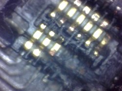
I just received my newest computer and it is liquid damage, as are most. But this one is different for me anyhow, as the damage is centered on the BIL connector it has pretty much corroded 1/2 the pins and they are gone not cleanable, gone. I keep looking at it, wondering what am I gonna do with this one? It runs great otherwise. Charges, runs, chimes. All the problems that is does have are associated with this connector like, not going into sleep mode, no battery indicator lights, no video.

My question is: Can I replace this? Are these parts available? if not, do I use one from another board i have for parts, and how would I do this without melting the connector. Any help out there would be appreciated. Thank you and again. what you all do here is so important.

Kathy

3996833_IMG-1607.jpg
 
Last edited:

rosscullen

macrumors newbie
Jan 23, 2013
2
0
Macbook Pro 13 A1278 Mid 2009

Hi Guys & Gals,

Do some IT work for a local charity in my hometown and got a Macbook Pro 13 A1278 Mid 2009 to look at. Upon examining the logic board thoroughtly, I noticed just one of the fuses burned out (even some of it on the bottom casing), which I believe said "+ 33 C90" on it (similar to others on the lb). Its probably a stupid question to most you on this forum but:

A) Can I purchase this component?
B) Would you think its just isolated to this or would there be something more wrong on the logicboard
C) where could I purchase this

Thank you for your time and help, sincerely appreciated
IMAG00200.jpg
 

cmdrdata

macrumors 6502
Jun 10, 2011
377
2
Dallas, Texas, USA
Hi Guys & Gals,

Do some IT work for a local charity in my hometown and got a Macbook Pro 13 A1278 Mid 2009 to look at. Upon examining the logic board thoroughtly, I noticed just one of the fuses burned out (even some of it on the bottom casing), which I believe said "+ 33 C90" on it (similar to others on the lb). Its probably a stupid question to most you on this forum but:

A) Can I purchase this component?
B) Would you think its just isolated to this or would there be something more wrong on the logicboard
C) where could I purchase this

Thank you for your time and help, sincerely appreciated
Image

The item shown in your picture is NOT a fuse. It is most likely a polarized capacitor(the + sign marking), perhaps 33 uF or 33 pF. if you looked at the same picture, there are a few more just like it in the lower left from the highlighted one. i don't know what caused the burn, so yes, you most likely have other problems too.
 

gretsch27

macrumors newbie
Feb 3, 2009
18
1
Bad battery?

I have a water damaged MBP (15", mid 2009) that I am trying to fix. I have cleaned the logic board with isopropyl alcohol and replaced the DC in board with a new one. I now have a green magsafe light, but I cannot start the machine even when I try jumping pin 5 to gnd on the keyboard connector. The magsafe indicator just stays green even though the battery is totally dead. G3Hot reads 3.38V.

The "non-removable" battery reads zero volts. I guess that means it dropped below a certain threshold. Does the battery have to supply any voltage for the machine to start? My brother's 2011 13" MBP can start with the battery removed. I did clean a small amount of corrosion off of the battery connector on the battery side (not the logic board side) so I suppose the battery could be junk.

I measured ~16.5 volts at the two diodes near the battery connector. I have measured 12V on multiple components on the board, so I'm certain that the DC-in board and the nearby fuse are ok.

Anyone have any ideas?
 

gretsch27

macrumors newbie
Feb 3, 2009
18
1
More info

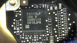
Another question... is this the SMC chip? (see picture below). I checked the voltages at several points coming off the chip and I got either 3.42V or 0V.

According to the schematics I found for the previous generation 15" unibody, pin 4 on the keyboard connector is G3HOT, while pin 5 is the on/off switch. When I measure pin 4, I get 3.42, and pin 5 is 3.38. Not sure why there is a difference there.

My guess is that the SMC chip is ok. The SMS bypass did not work for me, so I believe that reinforces the point that the SMC is not the problem. I have power at various points on the board, so I do not think it is a problem with a blown fuse.

I am at a loss as to why this thing won't turn on.
 

Attachments

  • photo.JPG
    photo.JPG
    213.3 KB · Views: 323

Techkat

macrumors member
Jan 23, 2013
33
0
Paso Robles, California
Some Very Helpful Information

I was searching for some information when I came across this information. It explains the power sequence of the apple macbook pro logic boards. It was in chinese. So I spent some time and translated it using the translation tools available in google, microsoft, etc. I left it exactly as it was translated. Sometimes when I did translate it I would try it in the other translator and it would be worded a little different. If any of you find this 32 page pdf helpful I was wondering if some the electronic wizards in the forum, when they have time, could make some edits and I will redo the corrections and post that one.

I left all the original info in there so that you can explore the site if you so desire.

I also have the original chinese version I will also post the link to. I am storing them on my file storage in my godaddy account. So its safe. Let me know wht you think.

1. Apple Power Sequence

2. Apple Power Sequence Original Chinese


Oh and if anyone has any information on my post above I would appreciate it, it all works great except the battery lights and the sleep mode. Battery lights I can live without but the sleep mode is kind of important. I am just afraid of trying to mess with the bad one unless someone with experience has any suggestions. Thank you again
 
Last edited:

cmdrdata

macrumors 6502
Jun 10, 2011
377
2
Dallas, Texas, USA
I was searching for some information when I came across this information. It explains the power sequence of the apple macbook pro logic boards. It was in chinese. So I spent some time and translated it using the translation tools available in google, microsoft, etc. I left it exactly as it was translated. Sometimes when I did translate it I would try it in the other translator and it would be worded a little different. If any of you find this 32 page pdf helpful I was wondering if some the electronic wizards in the forum, when they have time, could make some edits and I will redo the corrections and post that one.

I left all the original info in there so that you can explore the site if you so desire.

I also have the original chinese version I will also post the link to. I am storing them on my file storage in my godaddy account. So its safe. Let me know wht you think.

1. Apple Power Sequence

2. Apple Power Sequence Original Chinese


Oh and if anyone has any information on my post above I would appreciate it, it all works great except the battery lights and the sleep mode. Battery lights I can live without but the sleep mode is kind of important. I am just afraid of trying to mess with the bad one unless someone with experience has any suggestions. Thank you again

If you have the MBP with "non-removable battery", check the tiny/small ribbon cable that comes from the BIL/sleep sensor. This flex cable is routed very close to the battery mounting screw and could be inadvertently torn when the battery screw is installed.

BTW, thanks for the documents you uploaded. I think it is a good document describing the power sequencing of most MBPs ,no matter what screen size.
 

rosscullen

macrumors newbie
Jan 23, 2013
2
0
The item shown in your picture is NOT a fuse. It is most likely a polarized capacitor(the + sign marking), perhaps 33 uF or 33 pF. if you looked at the same picture, there are a few more just like it in the lower left from the highlighted one. i don't know what caused the burn, so yes, you most likely have other problems too.

Hey Hey cmdrdata

Thanks for the info. Any idea where i'd source a suitable capacitor to replace it? Tks
R
 

cmdrdata

macrumors 6502
Jun 10, 2011
377
2
Dallas, Texas, USA
Hey Hey cmdrdata

Thanks for the info. Any idea where i'd source a suitable capacitor to replace it? Tks
R

Someone in this group probably have a parts board that he/she can pull out a capacitor like yours for ya. HOWEVER, I'd doubt that it will resurrect your logic board just by replacing this part. Most caps of that size are probably acting as smoothing filters and not the cause of your system not powering up. You've got more serious problem and I really don't know where to begin.

EDIT: I looked around a typical MBP13 schematic, and I believe capacitors with those markings ( [plus sign] C90 33) are 330 uF filter caps used to generate and smooth out 5v, 3.3v, and 1v so they are quite critical in providing these supply levels. So yes, you will have to replace the bad ones first before going on rto the next troubleshooting effort.
 
Last edited:

cmdrdata

macrumors 6502
Jun 10, 2011
377
2
Dallas, Texas, USA
Thanks so much for getting back to me! I found VREG5 with no Voltage (should be 5V??) Also, no voltage at Q7930. I don't have a schematic so i can't trouble the 3v/5v supply.

Here's the PDF version of the 5v/3.3v supply you asked.
 

Attachments

  • MBP13 L2010-K92-page66.pdf
    51.9 KB · Views: 831

Musicsoul78

macrumors regular
Aug 24, 2012
111
0
UK ESSEX
general question

what main components if damaged can generally change the resistance values of most components/resisters/fuses??

when comparing 2 identical boards i found this to be the case..

if you could pin point problematic areas...

great little guide
 

Techkat

macrumors member
Jan 23, 2013
33
0
Paso Robles, California
what main components if damaged can generally change the resistance values of most components/resisters/fuses??

when comparing 2 identical boards i found this to be the case..

if you could pin point problematic areas...

great little guide

I myself when I had a problem similar I found the computer I just received had a shorted gpu. I am not an expert in the area by a long shot only know what I've learned from necessity. Have you checked to see if you have a short on the board. That was what my problem was.
 

Techkat

macrumors member
Jan 23, 2013
33
0
Paso Robles, California
If you have the MBP with "non-removable battery", check the tiny/small ribbon cable that comes from the BIL/sleep sensor. This flex cable is routed very close to the battery mounting screw and could be inadvertently torn when the battery screw is installed.

BTW, thanks for the documents you uploaded. I think it is a good document describing the power sequencing of most MBPs ,no matter what screen size.

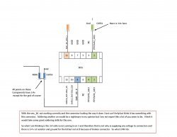
Hi CMDR, I have been so busy no time to get back to you.. When you told me to check cable, I at first thought no because if you look at picture on the top The connector is messed up. Last night I checked it anyhow and there were no kinks but when I removed it and looked at it, I found quite a bit of buildup, Alkaline or something from water damage. Thats what happened to connector above. So when I removed it I found an answer to a Problem I really didn't know what I had. The battery I assumed needed replacing because it would start charging a charge for a little and the osx said to replace and sometimes it would say not there. When I removed the cable in which you are speaking of it charges just fine. I guess I didn't need to order battery (lesson learned)
but It still won't go to sleep when lid is closed. I can't help but feel that connector has a lot to do with it. Ive attached a little drawing and some more pictures. If anyone has suggestions.
 

Attachments

  • SMC.jpg
    SMC.jpg
    177 KB · Views: 480
  • Still0005.jpg
    Still0005.jpg
    272.6 KB · Views: 271
Last edited:

Musicsoul78

macrumors regular
Aug 24, 2012
111
0
UK ESSEX
I myself when I had a problem similar I found the computer I just received had a shorted gpu. I am not an expert in the area by a long shot only know what I've learned from necessity. Have you checked to see if you have a short on the board. That was what my problem was.
ty

keep them coming


your macbook pro proble
btw i had the same problem with a 15inch
had to perm disconect that ribon cable to allow thw batery to charge.
how ever i was still allowed to sleep.

is the screen original ... because if the screen is swapped out from different model the magnets will not align correctly therefore not triggering sleep mode.

Dadioh knows a work around or test for this with a magnet....
 
Last edited:

cmdrdata

macrumors 6502
Jun 10, 2011
377
2
Dallas, Texas, USA
Hi CMDR, I have been so busy no time to get back to you.. When you told me to check cable, I at first thought no because if you look at picture on the top The connector is messed up. Last night I checked it anyhow and there were no kinks but when I removed it and looked at it, I found quite a bit of buildup, Alkaline or something from water damage. Thats what happened to connector above. So when I removed it I found an answer to a Problem I really didn't know what I had. The battery I assumed needed replacing because it would start charging a charge for a little and the osx said to replace and sometimes it would say not there. When I removed the cable in which you are speaking of it charges just fine. I guess I didn't need to order battery (lesson learned)
but It still won't go to sleep when lid is closed. I can't help but feel that connector has a lot to do with it. Ive attached a little drawing and some more pictures. If anyone has suggestions.

That connector looked damaged pretty bad. I think you have to somehow repair connectivity so that pins 1,2 and 4 can provide G3HOT (3.42v) to the BIL flex cable connector. You also need to ensure that the common end of R696? and C6955 have continuity to pin8 of that mating plug. My guess is that the Sleep signal on pin8 goes to ground when the lid is closed, and thus pulls the 3.4v you read on R696? to ground after a delay when C6955 finally discharged to 0v. Grounding pin8 of the connector (if the circuit trace is ok) on that connector directly to GND when the system is up should tell the system to sleep (I think R696? is a pull up resistor to keep that line at logic 1 when not being being "told" to sleep). The SMC "talks" to the battery via the SCL/SDA lines and that is how it knows battery status as well as charge state.
 

Techkat

macrumors member
Jan 23, 2013
33
0
Paso Robles, California
Thank you

That connector looked damaged pretty bad. I think you have to somehow repair connectivity so that pins 1,2 and 4 can provide G3HOT (3.42v) to the BIL flex cable connector. You also need to ensure that the common end of R696? and C6955 have continuity to pin8 of that mating plug. My guess is that the Sleep signal on pin8 goes to ground when the lid is closed, and thus pulls the 3.4v you read on R696? to ground after a delay when C6955 finally discharged to 0v. Grounding pin8 of the connector (if the circuit trace is ok) on that connector directly to GND when the system is up should tell the system to sleep (I think R696? is a pull up resistor to keep that line at logic 1 when not being being "told" to sleep). The SMC "talks" to the battery via the SCL/SDA lines and that is how it knows battery status as well as charge state.

Thank you guys for the response. I feel like I know you guys really well because I have followed this post for awhile now. You are all regulars. I just wanted to throw something out there to see what you guys think of the idea.

The information here is invaluable but if you have to go back and through the old posts looking for something you remember you read sometimes that has been difficult or if you read these posts much later than written. You have to really pay attention that the next one you are reading is not the the post you are interested in. I don't know how many times I did that when I first found this wonderful place.

Anyhow I've been entertaining the thought of putting the very valuable information in here into something whether it be a pdf a word doc. or I have even entertained the idea of putting a database. I would do the work so that all could enjoy I would need some help on input and ways to go from time to time. I know its a big task to undertake but do you think it would be worth it. What I have done ( might be a tip for you) is just print the 50 plus pages as a pdf it makes it very searchable I have the pro version of adobe. but its still not what I was picturing in my head yet. Would appreciate the input if anyone feels this would be helpful.

Thank you for getting back to me I am going to get back on these wonderful suggestions. Let you know how it goes
 

Techkat

macrumors member
Jan 23, 2013
33
0
Paso Robles, California
Music to my ears

ty

keep them coming


your macbook pro proble
btw i had the same problem with a 15inch
had to perm disconect that ribon cable to allow thw batery to charge.
how ever i was still allowed to sleep.

is the screen original ... because if the screen is swapped out from different model the magnets will not align correctly therefore not triggering sleep mode.

Dadioh knows a work around or test for this with a magnet....

Thank you for your response Music. Okay so if I listen to what you are saying you are telling me that you had cable connector off and it didnt effect the sleep of computer. Okay so if I take what you and Cmr are telling me I think we have the answer. It doesnt rely on the connector because we all know the switch is other end with hard drive. so if magnet is good (I know how to check that I didnt think of it till you said. Pretty much like alarm systems on doors and windows the magnet breaks. normally open alarms and normally closed computers. (if I understand it right) ok so if magnet good then it has to be in trace most likely, it could be other things but its a good probablity the problem is staring right in face. I guess it was wine damage and from what I see they left it. Thank you all again.
 

unknown11

macrumors newbie
Jan 29, 2013
9
0
What do you think?

Hi all,

First off I'd like to thank all those who contributed to this forum. It's been an invaluable resource in my learning and understanding of this topic that I previously knew close to nothing about beforehand. It took a lot of time and effort to get to this point but I think I've figured it out. And so I'm praying one of you can help me here in restoring my Macbook pro. This is my story:

-Early 2011 13" Macbook Pro MC724ll/a (a1278)
-Woke up the morning after Hurricane Sandy to find it with No sign of life. -No Magsafe light.
-No response to power button (tried magsafe+battery, battery only, magsafe only)
-Would later try but get No response to SMC reset, or SMC bypass.
-Also tried with RAM, No RAM, one RAM, different RAM. Same for HD.
-It had no external damage of any kind so after doing some research I thought a surge might have blew out the magsafe power adapter or DCIN board. I swapped those with known good ones but still no sign of life.
-Next, I inspected the logic board to find no obvious signs of damage or debris, but gave it an isopropyl alcohol scrub anyway. No dice.

So with no warranty, no money for logic board repair, and certainly no money for a new one, I picked up a multimeter from radioshack to see how far I can get on my own. Using the information from this forum as a guild, I identified these abnormalities:

1) Pins 2 & 4 on DCIN board, Pins 1 & 2 at DCIN jack on Logic board, and the main board fuse (F6905), all only = 0.19V (meter set to 20V). Same is true for other areas of the board where PPDCIN_G3H is the input.
-DCIN board Pins 1,3,5 and DCIN jack pins 3,4,5 on LB = 0V

2) G3HOT 3.425V is obviously not being enabled from the DCIN so I tried a known functional fully charged battery, but still no G3HOT. All I got from the battery was: pins 1-3 = 0V, pins 4&6 = 0.002V, pin 5 = fluctuation between 0.00-0.06V, and pins 7-9 = only ~0.20V. PIN 5 at Q7055 is also ~0.20V but pins 1-3 read ~0.12V. This also gives the fuse near the battery (F7040) ~0.12V. Therefore, PPBUS_G3H and the areas where it is an input were also measured at ~0.12V.

3) These numbers are the same when both battery and magsafe are plugged in together. Still no G3HOT. No voltage at U6900. No ADAPTER_SENSE signal.

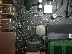
Now with these numbers and G3HOT not being enabled, I thought something must be off with at least U6990 but I couldn't find it on my board. I had been using an out dated schematic that was posted in this forum a while back to find most of these components under the assumption that not much has changed in the circuitry, but that was false. I finally came across the schematic for my board, 820-2936 (attached below). With this I was finally able to track down and identify U6990 and also identify one major component that is different from the early board/schematic; D6990!!!! I tracked both PPBUS_G3HOT and PPDCIN_G3HOT going into the anodes of D6990 and measured their respective voltages, PPBUS= ~0.12V PPDCIN= ~ 0.19V. But I only got fluctuating 0-0.002V coming out the shared cathode. I'm guessing this is not enough to signal U6990 to enable PP3V42_G3H. From the naked eye this component does not look fried (red box around it in the picture below).

So now that you've heard the entire story here are my questions:
-Does this seem like sufficient evidences to assume that the D6990 is the cause of my power issues?
-What else can I do to confirm or contradict this theory?
-Am I even right to assume that going through D6990 to get to U6990 is the only way to get PP3V42_G3H and thus prodive power to the board?
-Is there anyway this could still be a problem with U6990, U7000, SMC, or other?

Sorry for the length. I'm just trying to be thorough. Any help is greatly appreciated. And thanks again to Dadioh for starting this awesome forum.
 

Attachments

  • a1278 K90i schematic.pdf
    1.7 MB · Views: 516
  • photo (1).JPG
    photo (1).JPG
    2.3 MB · Views: 1,111
  • photo.PNG
    photo.PNG
    74.9 KB · Views: 512

cmdrdata

macrumors 6502
Jun 10, 2011
377
2
Dallas, Texas, USA
Hi all,

First off I'd like to thank all those who contributed to this forum. It's been an invaluable resource in my learning and understanding of this topic that I previously knew close to nothing about beforehand. It took a lot of time and effort to get to this point but I think I've figured it out. And so I'm praying one of you can help me here in restoring my Macbook pro. This is my story:

-Early 2011 13" Macbook Pro MC724ll/a (a1278)
-Woke up the morning after Hurricane Sandy to find it with No sign of life. -No Magsafe light.
-No response to power button (tried magsafe+battery, battery only, magsafe only)
-Would later try but get No response to SMC reset, or SMC bypass.
-Also tried with RAM, No RAM, one RAM, different RAM. Same for HD.
-It had no external damage of any kind so after doing some research I thought a surge might have blew out the magsafe power adapter or DCIN board. I swapped those with known good ones but still no sign of life.
-Next, I inspected the logic board to find no obvious signs of damage or debris, but gave it an isopropyl alcohol scrub anyway. No dice.

So with no warranty, no money for logic board repair, and certainly no money for a new one, I picked up a multimeter from radioshack to see how far I can get on my own. Using the information from this forum as a guild, I identified these abnormalities:

1) Pins 2 & 4 on DCIN board, Pins 1 & 2 at DCIN jack on Logic board, and the main board fuse (F6905), all only = 0.19V (meter set to 20V). Same is true for other areas of the board where PPDCIN_G3H is the input.
-DCIN board Pins 1,3,5 and DCIN jack pins 3,4,5 on LB = 0V

2) G3HOT 3.425V is obviously not being enabled from the DCIN so I tried a known functional fully charged battery, but still no G3HOT. All I got from the battery was: pins 1-3 = 0V, pins 4&6 = 0.002V, pin 5 = fluctuation between 0.00-0.06V, and pins 7-9 = only ~0.20V. PIN 5 at Q7055 is also ~0.20V but pins 1-3 read ~0.12V. This also gives the fuse near the battery (F7040) ~0.12V. Therefore, PPBUS_G3H and the areas where it is an input were also measured at ~0.12V.

3) These numbers are the same when both battery and magsafe are plugged in together. Still no G3HOT. No voltage at U6900. No ADAPTER_SENSE signal.

Now with these numbers and G3HOT not being enabled, I thought something must be off with at least U6990 but I couldn't find it on my board. I had been using an out dated schematic that was posted in this forum a while back to find most of these components under the assumption that not much has changed in the circuitry, but that was false. I finally came across the schematic for my board, 820-2936 (attached below). With this I was finally able to track down and identify U6990 and also identify one major component that is different from the early board/schematic; D6990!!!! I tracked both PPBUS_G3HOT and PPDCIN_G3HOT going into the anodes of D6990 and measured their respective voltages, PPBUS= ~0.12V PPDCIN= ~ 0.19V. But I only got fluctuating 0-0.002V coming out the shared cathode. I'm guessing this is not enough to signal U6990 to enable PP3V42_G3H. From the naked eye this component does not look fried (red box around it in the picture below).

So now that you've heard the entire story here are my questions:
-Does this seem like sufficient evidences to assume that the D6990 is the cause of my power issues?
-What else can I do to confirm or contradict this theory?
-Am I even right to assume that going through D6990 to get to U6990 is the only way to get PP3V42_G3H and thus prodive power to the board?
-Is there anyway this could still be a problem with U6990, U7000, SMC, or other?

Sorry for the length. I'm just trying to be thorough. Any help is greatly appreciated. And thanks again to Dadioh for starting this awesome forum.

Nope I doubt if the problem is U6990. The input sources to G3HOT are magsafe and battery. Since you are NOT getting raw DCIN 16.5v from magsafe at the 5-pin DCIN board or 12v at pins 7/8/9 of the battery, I think you WILL never get 3.4v. These two input sources are directly connected to the diode pair with common cathode, so if one of them is present, then U6990 will come into play. Figure out why battery power is not at pin 7/8/9. Typically, on an MBP of that vintage pin5 should be 0v, and thus the battery output is in an enabled state.

PS: My bet (a cup of virtual Starbuck coffee) is that there is nothing wrong with the MBP itself. I think you've still got a defective magsafe and a depleted battery that preserve itself by shutting down its output.
 
Last edited:

unknown11

macrumors newbie
Jan 29, 2013
9
0
Nope I doubt if the problem is U6990. The input sources to G3HOT are magsafe and battery. Since you are NOT getting raw DCIN 16.5v from magsafe at the 5-pin DCIN board or 12v at pins 7/8/9 of the battery, I think you WILL never get 3.4v. These two input sources are directly connected to the diode pair with common cathode, so if one of them is present, then U6990 will come into play. Figure out why battery power is not at pin 7/8/9. Typically, on an MBP of that vintage pin5 should be 0v, and thus the battery output is in an enabled state.

PS: My bet (a cup of virtual Starbuck coffee) is that there is nothing wrong with the MBP itself. I think you've still got a defective magsafe and a depleted battery that preserve itself by shutting down its output.

I wish this were the case but it seems HIGHLY unlikely. I've tried 3 different magsafes, all of which work fine in powering up and charging the battery of another board I have. Same with the 2 batteries I have. I charged them both fully, then tried them in the above mention board but get the same result for both.
So they work, but why aren't they working in this board? The fact that U6990 isn't receiving any signal because of no conduction through D6990 doesn't sound alarming? Wouldn't that explain why the battery remains shut down and why the magsafe doesn't output the full 16.5V? because there's no PP3V42_G3H being generate to feedback to magsafe and battery to tell them it's ok to disperse 16.5V and 12V, respectively?
 

cmdrdata

macrumors 6502
Jun 10, 2011
377
2
Dallas, Texas, USA
I wish this were the case but it seems HIGHLY unlikely. I've tried 3 different magsafes, all of which work fine in powering up and charging the battery of another board I have. Same with the 2 batteries I have. I charged them both fully, then tried them in the above mention board but get the same result for both.
So they work, but why aren't they working in this board? The fact that U6990 isn't receiving any signal because of no conduction through D6990 doesn't sound alarming? Wouldn't that explain why the battery remains shut down and why the magsafe doesn't output the full 16.5V? because there's no PP3V42_G3H being generate to feedback to magsafe and battery to tell them it's ok to disperse 16.5V and 12V, respectively?

On diode pair D6990, do you see 16.5v on one anode and 12v on the second anode? If one of these is present, then you can suspect the U6990 as being bad or that diode pair itself as being bad. If you looked at the schematic, notice that the 16.5v comes directly from the magsafe to this diode pair through a series resistor. The 12v on the other hand is connected directly to the +v of the battery. So if at least one of these is present, G3HOT will then be available. The reason it is called G3HOT is because it is supposed to be always available (HOT) even when the system is off but connected to magsafe or battery. Also notice pin5. when the battery is plugged in, pin5 is then connected thru a 10K(?) resistor to ground. This signal tells the battery that it is connected to the system and tells it to enable its 12v output. The fact that you see 0.x volts at 7/8/9, tells me that the battery is in self shutdown mode, to protect the Li-ion cells from dropping to below a safe threshold.

Have you done an SMC reset?
 

unknown11

macrumors newbie
Jan 29, 2013
9
0
On diode pair D6990, do you see 16.5v on one anode and 12v on the second anode? If one of these is present, then you can suspect the U6990 as being bad or that diode pair itself as being bad. If you looked at the schematic, notice that the 16.5v comes directly from the magsafe to this diode pair through a series resistor. The 12v on the other hand is connected directly to the +v of the battery. So if at least one of these is present, G3HOT will then be available. The reason it is called G3HOT is because it is supposed to be always available (HOT) even when the system is off but connected to magsafe or battery. Also notice pin5. when the battery is plugged in, pin5 is then connected thru a 10K(?) resistor to ground. This signal tells the battery that it is connected to the system and tells it to enable its 12v output. The fact that you see 0.x volts at 7/8/9, tells me that the battery is in self shutdown mode, to protect the Li-ion cells from dropping to below a safe threshold.

Have you done an SMC reset?

I'm only getting that very low 0.19V from the magsafe at one anode, and only ~0.12V from the battery at the other anode. And again, nothing coming out the cathode. I can't understand how I can take a battery that functions normally in one board (w/12V output at pins 7-9), as well as a magsafe that was just outputting 16.5V in said board, then hook them up to this problematic board and get almost no output from either. I've tried the SMC reset and the temporary bypass but they didn't work.

Is there any other possible explanation for this lack of output from these known functioning magsafe and battery? Could there be a short somewhere on the board I'm not thinking of that could cause this? Could there be a problem with the jacks(but what are the chances both are compromised)?

I get what your saying about pin 5, but wouldn't the system need power in the first place to be able to generate a signal that would enable the battery to output 12V? This makes me still think that if there is no signal getting to U6990 (possibly because of defected D6990) then theres no G3HOT to power that system. No power to the system = no feedback to the magsafe or battery, making them acted as if they aren't connected to anything or just simply remain in their shutdown modes. Just like when you plug in the magsafe to a stand alone magsafe DCIN board not plugged into the logic board. You may get an initial 4.xx volts but then it drops off to 0.xx volts.

Is my reasoning a possibility at all? Or am I just way off with this one?
Thank you cmdrdata. I appreciate you taking the time to help me out here.
 

cmdrdata

macrumors 6502
Jun 10, 2011
377
2
Dallas, Texas, USA
I'm only getting that very low 0.19V from the magsafe at one anode, and only ~0.12V from the battery at the other anode. And again, nothing coming out the cathode. I can't understand how I can take a battery that functions normally in one board (w/12V output at pins 7-9), as well as a magsafe that was just outputting 16.5V in said board, then hook them up to this problematic board and get almost no output from either. I've tried the SMC reset and the temporary bypass but they didn't work.

Is there any other possible explanation for this lack of output from these known functioning magsafe and battery? Could there be a short somewhere on the board I'm not thinking of that could cause this? Could there be a problem with the jacks(but what are the chances both are compromised)?

I get what your saying about pin 5, but wouldn't the system need power in the first place to be able to generate a signal that would enable the battery to output 12V? This makes me still think that if there is no signal getting to U6990 (possibly because of defected D6990) then theres no G3HOT to power that system. No power to the system = no feedback to the magsafe or battery, making them acted as if they aren't connected to anything or just simply remain in their shutdown modes. Just like when you plug in the magsafe to a stand alone magsafe DCIN board not plugged into the logic board. You may get an initial 4.xx volts but then it drops off to 0.xx volts.

Is my reasoning a possibility at all? Or am I just way off with this one?
Thank you cmdrdata. I appreciate you taking the time to help me out here.

I cracked open one of this MBP battery pack a couple of years ago. Inside it are 6 flat Li-ion batteries with a small circuit board powered by this battery pack. This tiny board is the one that sends serial data to the SMC when it is connected to the logicboard whenever SMC request status from it. BUT this tiny board also expects a 10K Ohm grounding signal, i.e., if you connect a 10K Ohm resistor between pin 5 and 1/2/3 away from the MBP, if the battery is good and charged, you will be able to measure 12v on pin 7/8/9 of the battery plug/connector

So the sequence of events are this:
1. You plug in a good battery pack to the logicboard, which by default connects R6950 to pin5, thus providing it with a signal to turn on the 12v on to pins 7/8/9.
2. The 12v from BATT pins 7/8/9 goes to D6990 pin1 through Q7055, R7050 and F7040 (by this time the 12v is called PPBUS_G3H), and thus allowing G3HOT to be created. Once G3HOT is up, then the SMC can begin doing its thing like controlling other power sequencing, doing serial comm, etc.
 

unknown11

macrumors newbie
Jan 29, 2013
9
0
I cracked open one of this MBP battery pack a couple of years ago. Inside it are 6 flat Li-ion batteries with a small circuit board powered by this battery pack. This tiny board is the one that sends serial data to the SMC when it is connected to the logicboard whenever SMC request status from it. BUT this tiny board also expects a 10K Ohm grounding signal, i.e., if you connect a 10K Ohm resistor between pin 5 and 1/2/3 away from the MBP, if the battery is good and charged, you will be able to measure 12v on pin 7/8/9 of the battery plug/connector

So the sequence of events are this:
1. You plug in a good battery pack to the logicboard, which by default connects R6950 to pin5, thus providing it with a signal to turn on the 12v on to pins 7/8/9.
2. The 12v from BATT pins 7/8/9 goes to D6990 pin1 through Q7055, R7050 and F7040 (by this time the 12v is called PPBUS_G3H), and thus allowing G3HOT to be created. Once G3HOT is up, then the SMC can begin doing its thing like controlling other power sequencing, doing serial comm, etc.

Sounds like a plan. I will give it a try hopefully by this weekend. I'll keep you posted.
 

Musicsoul78

macrumors regular
Aug 24, 2012
111
0
UK ESSEX
Thank you for your response Music. Okay so if I listen to what you are saying you are telling me that you had cable connector off and it didnt effect the sleep of computer. Okay so if I take what you and Cmr are telling me I think we have the answer. It doesnt rely on the connector because we all know the switch is other end with hard drive. so if magnet is good (I know how to check that I didnt think of it till you said. Pretty much like alarm systems on doors and windows the magnet breaks. normally open alarms and normally closed computers. (if I understand it right) ok so if magnet good then it has to be in trace most likely, it could be other things but its a good probablity the problem is staring right in face. I guess it was wine damage and from what I see they left it. Thank you all again.

anytime and goodluck

if you fix let us know what part of the board that your specific case was effected. providing knowledge for others is key

thanks

----------

Sounds like a plan. I will give it a try hopefully by this weekend. I'll keep you posted.

you have probably already done this but have you checked the 2 6a fuses.

2 big white fuses one on each side of your 2011 model

1 by the battery

and 1 by the dc jack underside of logic board


sometimes its the the simple things!
 
Last edited:
Register on MacRumors! This sidebar will go away, and you'll see fewer ads.