Become a MacRumors Supporter for $50/year with no ads, ability to filter front page stories, and private forums.
Please specify Logic board part number or type if possible

Hi,

To all those needing specific logic board assistance please can you specify the part number of the board, this will be an embossed number actually written on the logic board itself, usually starts with a 820 number OR the board type number that is sometimes written on a label which is stuck to the RAM socket. These numbers are sometimes written as K6, K2, M97.

These numbers will help us a lot when trying to determine what help we can provide. The reason being is due to the fact that there are so many different types of A1286 or A1278 and other models, which have different logic boards in them, so just saying you have a faulty A1286 does not help much because the logic board inside could be 3 or 4 different types which all have different circuits and schematics.

Could you also please search the thread because some people are asking the same questions over and over. I've not replied to some asking for help because I know the answer is in the thread but they have not searched the thread. I know some who help are retired and on occasion have time to help but speaking for myself here, I work full time fixing not only apple logic boards but other types too so I don't have the time to answer repeat questions, sorry if this sounds too arrogant. I will do my best to help where I can.

regards
Rog

Sorry Rog

Mines an
820-2936-B

Hope you can help.

Kindest regards
Simon
 
I have tried that but still the same. I have take voltage readings from the power board to the main board and all reads fine. I'm just unsure where else on the main logic board to take readings and location of fuses as my board being late 2010 to early 2011 is different from those mentioned in earlier posts on this thread.
Any help would be great fully appreciated please.

Kindest regards
If your LCD connecter is angled on the board then it it should be the early 2011 MBP.The schematic & board view file has been posted on this thread or Dadioh's "No Back-light Thread". It's the K90i 820-2936B file your looking for.I don't think its gonna be as simple as a fuse.In some cases a drop will either cause cracked solder ball's under the GPU,CPU,ETC...or even crack the board or traces on the board.I really don't know what you could do next.Maybe some one with more experience can help from here.
Good luck
 
DC-in Board MacBook Pro A1278

Does anybody have or have seen the schematic for the small DC-in board for MBP Early 2011 13'?

Part# 820-2565-A

I'm trying to fix it and I know this is the DC-in board issue, the LED light does not come up and the middle pin 3 supposed to be 3.4V but I'm getting 16V.

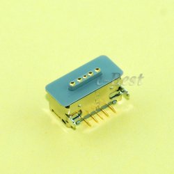
I checked few small caps and resistor also the diode which were all tested ok compared to my fully working DC-in board. Now, I'm suspecting it might the DC power jack socket (picture below) but without the schematic it is always hard to troubleshoot. It strange that Apple didn't include this on the main schematic for the whole LB...:(
 

Attachments

  • $T2eC16NHJGQE9noMZGd5BQRw8VeF,Q~~60_3.jpg
    $T2eC16NHJGQE9noMZGd5BQRw8VeF,Q~~60_3.jpg
    180.1 KB · Views: 404
Last edited:
Please help guys. Urgently needed.

I have a 2010 MacBook pro A1278
And after a short fall off my bed it no longer powers up.
I have tried everything ( SMC reset , PMU reset. Ect ect) but nothing.
The MagSafe light is green and the battery indicator shows green nearly full.

I have tried jumping the power switch ect but no signs of life.

Any ideas if there's a fuse somewhere maybe? And location. Or what else it might be.

Cheers in advance guys I'm so desperate to get this back up and running to Finish my exams.

Regards
Sy


firstly, as already mentioned, the boardview and schematic for your board can be found in this thread or in the 'backlight issue' thread. Be careful though as there are two 820-2936 schematics, one is 271kb in size and the other is 1.63mb, you need the 1.63mb file as this is the complete schematic, the other one has many pages missing.

CAUTION!!!! When trying to connect the magsafe connector to the DC connector which connects to the logic board, it is easy to get them misaligned and can cause sparks, shorts and even pin damage (magsafe has 5 pins). Constant plugging of the magsafe to the logic board in quick succession can cause voltage spikes which will cause damage to some of the electronic components on the logic board. In my opinion, the best practice is once you have connected the magsafe to the DC connector and you see the green led, don't touch the magsafe but remove the mains lead from AC adapter. If you need to remove the magsafe due to constant turning of the logic board, unplug the DC connector from the logic board, that way, both magsafe and dc connector always stays aligned and when you need to provide power to the board, just plug in the DC connector to the board and the mains lead to the AC adaptor. With that in mind you can move to the next part below.

Now, as I assume you have the logic board removed from the chassis. Make sure nothing else is connected to the logic board apart from the magsafe connector, remove the RAM. Connect the magsafe to it's mating half. Make sure the magsafe led turns green (your post mentions it does go green when connected). This means the important G3HOT supply is working which means both fuses F7040 & F6905 are OK because if both or either of those fuses had fail, you would not get the green led on the magsafe. Now, due to everything else being removed, do an initial power on check. This mean plug connect the RAM, the fan and the speak, and of course the DC connector. To power on the board, using a pair of tweezers or other fine tipped metal tool, you need to short one of the pins on the keyboard connector to ground, I have already submitted a post with a diagram showing which pin, you need to find that post. The pin you short is effectively the power button on the keyboard. If the fan does not spin, you need to removed the DC connector but make sure you remove the mains plug from the AC adaptor first. NEVER remove the DC connector from the logic board while the magsafe led is green. Now you've completed that step, the magesafe removed, connect your battery and repeat the power on method. If still no fan spin then the SMC is not functioning properly because that is what controls the power on function of the logic board.

Carry out the above and get back to me on what you find.

regards
Rog

PS. please note it's the weekend and therefore my day of so I might not reply as quickly as you might like.
 
It would appear as though U6990 is faulty but measure both pin#9 & pin#6 their resistance to ground to make sure that nothing it pulling those pins to ground, your meter should read 'OL'. As for the backlight, the voltages of those pins you measured is wrong, pin#21 & pin#22 ( PPVOUT_SW_LCDBKLT ) should both be 27v. Check to make sure the fuse F9700 supplying voltage to lcd controller IC U9701 is OK

Thanks for the info!

The fuse F9700 is OK and I measured 11.5V there. Is this right?
What voltage do I expect here?

Regarding the backlight I measured 2.7V with BKL_EN on U9701,
which, guessed from the predeccesors, is enough (they needed at least
1.6V IIRC). SW and FB both lie around 11.5V.

However, PP3V3_S0, measures on C9711 only 3V instead of the expected
3.3V. Also, PP5V_S0 measures 4.64V instead of 5V (on C9714).
Which voltages do I expect on PP3V3_S0 and PP5V_S0 normally?

Also, I'm a bit confused about the specs of the U9701 (TI LP8550)
which is saying that it needs at least 5.5V on VIN.
Shouldn't PP5V_S0 be PP5V5_S0 then? Or is the spec lying?
Or have I got the wrong product number?

EDIT #1: I measured from PP3V3_S0 to GND and found a 13.1 kOhm resistance (steady).
For PP5V_S0 it is the same with 10 kOhm.

It is also noteworthy that PPBUS_G3H is not 12.8V but 12.25V or less, i.e. 11.9V
(measured at F7040).
 
Last edited:
Thanks for the info!

The fuse F9700 is OK and I measured 11.5V there. Is this right?
What voltage do I expect here?

Regarding the backlight I measured 2.7V with BKL_EN on U9701,
which, guessed from the predeccesors, is enough (they needed at least
1.6V IIRC). SW and FB both lie around 11.5V.

However, PP3V3_S0, measures on C9711 only 3V instead of the expected
3.3V. Also, PP5V_S0 measures 4.64V instead of 5V (on C9714).
Which voltages do I expect on PP3V3_S0 and PP5V_S0 normally?

Also, I'm a bit confused about the specs of the U9701 (TI LP8550)
which is saying that it needs at least 5.5V on VIN.
Shouldn't PP5V_S0 be PP5V5_S0 then? Or is the spec lying?
Or have I got the wrong product number?

If you look at page 3 of the schematic you will see it links fuse F9700 to Q9706 which in turn connects to VIN of IC U9701 but when you look at page 77 you see VIN is actually connected to PP5V_S0 so it would appear there is a conflict of interest here. Due to the fact U9701 is a BGA chip you can't check for continuity between Q9706 and VIN of U9701 to prove which one of those pages is correct. The reason I said to check fuse 9700 for supply to the IC because I was going by what I saw on page 3.

I would stick to page 77, make sure you have 5v on PP5V_S0 and 12v on PPBUS_SW_LCDBKLT_PWR. As for your voltage readings, are you using a multimeter that uses batteries because it is possible the batteries are low hence the low readings? Check with a know voltage source to check how accurate your meter is. I would be expecting the odd one reading to be slightly off due to a fault with the voltage supply but all your readings are slightly off, hence my suspicion about your meter.

If you do get both those voltages at the points specified then I fear it is the IC that has gone faulty, and considering it is a BGA one, will be virtually impossible to change.

PS, just noticed the resistor on BLk_EN so that could be why u seeing 2v. Check the other side for 12v, it's late here and am going by memory as all my details are at work.
 
SMC Issue Macbook Air 2012

Dear Friend,
I have a problem with my MBA 2012.
I spilled tea on the MBA.
After thath it was running but no sound, Magsafe stay dark and the MBA was running really slow.
After cleaning the Logic Board with Isopropanol 100% and remov the corrosion, was the sound back.
If I bypass the SMC run the machine normal.
Until yesterday light the magsafe again.
Wath do you think, ist the SMC damaged or just durty? Can I change the SMC IC or must be programmed?
Thanks a lot for your help!
Best Regards.
 
Another success 820-2936-B

I've had another repair success. It is an I-series A1286, 820-2936-B. Fault symptoms were no battery charge (charge led stayed green) and no power on (pressing power button did nothing). I checked for all the main voltages and found that I had lost PP3V3_S5. With just the magsafe connected it should read 3.3v on the multimeter but i got 0v. Looking at the schematic, U7201 provides the 3.3v and 5v. The 5v is only present when the logic board powers on. The supply voltage to U7201 was ok so I knew it had to be a faulty IC. I replaced it with one from a scrapped board and when i checked at L7260 i was reading 3.3v. I connected the keyboard, added the RAM, fan and speaker, pressed the power button and the board powered up and I heard the boot chimes. Powered off the board, connected the LCD, powered on again and the LCD came to life with the flashing icon..success :)

regards
Rog
 
If you look at page 3 of the schematic you will see it links fuse F9700 to Q9706 which in turn connects to VIN of IC U9701 but when you look at page 77 you see VIN is actually connected to PP5V_S0 so it would appear there is a conflict of interest here. Due to the fact U9701 is a BGA chip you can't check for continuity between Q9706 and VIN of U9701 to prove which one of those pages is correct. The reason I said to check fuse 9700 for supply to the IC because I was going by what I saw on page 3.

I would stick to page 77, make sure you have 5v on PP5V_S0 and 12v on PPBUS_SW_LCDBKLT_PWR. As for your voltage readings, are you using a multimeter that uses batteries because it is possible the batteries are low hence the low readings? Check with a know voltage source to check how accurate your meter is. I would be expecting the odd one reading to be slightly off due to a fault with the voltage supply but all your readings are slightly off, hence my suspicion about your meter.

If you do get both those voltages at the points specified then I fear it is the IC that has gone faulty, and considering it is a BGA one, will be virtually impossible to change.

PS, just noticed the resistor on BLk_EN so that could be why u seeing 2v. Check the other side for 12v, it's late here and am going by memory as all my details are at work.

Wow, I feel a bit silly now. I haven't thought of the battieries in the multimeter at all, good one!
I've replaced them and I read 3.4V (3.39V) at G3Hot and ~16.8V at DCIN.
I think I have to measure everything all over again now.

Congratulations on your successful repair, though.

EDIT #1: Currently I'm measuring some voltages on the logic board,
which is connected the MagSafe board and nothing else. The board
is not powered on but the power supply is connected (dim green light).

G3Hot is between 3.38 and 3.39V. This seems to be in the error margin
but I'm not sure. Does it have to be exactly 3.425V?

ALL_SYS_PWRGD is logically 0, so is CPUIMVP_PGOOD.
SMC_RESET_L is logically 1 (~3.3V).

All always-on (G3Hot) lanes report the right(?) voltages:

- PPBUS_G3H (12.3V)
- PPVRTC_G3H (3.27V)
- PP3V42_G3H (3.38V)
- PPDCIN_G3H (16.79V)
- PPBUS_S5_HS_OTHER_ISNS (12.3V)
- PPBUS_S5_HS_COMPUTING_ISNS (12.3V) (measured at C7331)

Except for PPVIN_SW_T29BST which should be 12.8V but really
is 0.0V. The gate of Q3880 (T29BST_PWREN_DIV_L)
measures 11.81V and PPBUS_G3H is at 12.3V. Is this correct?
 
Last edited:
Wow, I feel a bit silly now. I haven't thought of the battieries in the multimeter at all, good one!
I've replaced them and I read 3.4V (3.39V) at G3Hot and ~16.8V at DCIN.
I think I have to measure everything all over again now.

Congratulations on your successful repair, though.

EDIT #1: Currently I'm measuring some voltages on the logic board,
which is connected the MagSafe board and nothing else. The board
is not powered on but the power supply is connected (dim green light).

G3Hot is between 3.38 and 3.39V. This seems to be in the error margin
but I'm not sure. Does it have to be exactly 3.425V?

ALL_SYS_PWRGD is logically 0, so is CPUIMVP_PGOOD.
SMC_RESET_L is logically 1 (~3.3V).

All always-on (G3Hot) lanes report the right(?) voltages:

- PPBUS_G3H (12.3V)
- PPVRTC_G3H (3.27V)
- PP3V42_G3H (3.38V)
- PPDCIN_G3H (16.79V)
- PPBUS_S5_HS_OTHER_ISNS (12.3V)
- PPBUS_S5_HS_COMPUTING_ISNS (12.3V) (measured at C7331)

Except for PPVIN_SW_T29BST which should be 12.8V but really
is 0.0V. The gate of Q3880 (T29BST_PWREN_DIV_L)
measures 11.81V and PPBUS_G3H is at 12.3V. Is this correct?

Wow, if you have A1278 / K90i 13" water damaged no POST/BOOT than we might have the same laptop with the same symptoms.

What voltages are you measuring on U7400-19 and U7400-10?

Mine are both 0V instead of 3.3V and 1.1V which means no power to CPU and GFX = no post.
 
If your MacBook is fully functional from the battery but not from the magsafe then the overvoltage protection circuit has got damaged. There will be no green led or battery charge orange led from the magsafe. The post from nemo points to one possible problem but in my experience this is very rare. When the charge IC ISL6295 goes faulty, it tends to go in a dramatic way which prevents the whole MacBook powering on, even from battery. I have not had one yet that has gone faulty and only pin#14 has been the problem, hence why in my opinion I believe ISL6295 is not the problem, but please do not discount this yet. The overvoltage protection circuit needs two control signals, one from the SMC and the other from the charge IC ISL6295. Usually when electronic components fail, they do so in a manner which damages 99% of the component which in the majority of cases the MacBook would never power on via magsafe or battery. Due to your MacBook fully working via the battery, this would indicate that the SMC and charge IC have to be working 100% BUT it is possible that both are working 99% and the 1% fail is due to both components loosing the control signal to the overvoltage protection circuit. On ALL the boards I have fixed that are fully functional via the battery and not the magsafe it has always been 1 or 2 components in the overvoltage protection circuit that has gone faulty.

To be able to pinpoint what actual parts possibly need replacing and a diagnostic tip on determining which part needs replacing I need to know specifically the logic board type. On the labels attached to the memory socket it will usually have an id like K6 or K24 or K90. If not then imprinted onto the logic board itself will be an 820- number. The reason is there are too many MacBook pro variants and some of the circuitry is different in certain models so we need to be sure as to which model of logic board you have so we can continue onto the next part, the diagnostic tip.

I see K24 on the ram socket sticker, and 820-2530-A on the board itself. Can you post a picture of the ISL6295? I think I found it, but just want to verify. I need to get a multi-meter to test it (any suggestions?). I haven't used one since college, mostly because I should have failed that class (I think the professor passed me so he wouldn't have to deal with me again :rolleyes: )
 
Wow, if you have A1278 / K90i 13" water damaged no POST/BOOT than we might have the same laptop with the same symptoms.

What voltages are you measuring on U7400-19 and U7400-10?

Mine are both 0V instead of 3.3V and 1.1V which means no power to CPU and GFX = no post.

Well, mine does boot if I bypass SMC and most of the things,
except for the backlight, are running fine (confirmed wifi),
so I doubt that our notebooks have exactly the same problem.

However, it might be related and I will do some measuring later.

Did you measure your reference voltages from earlier posts under the
same conditions as you measured the bad board? It would be good
to know if the battery was plugged in or magsafe only.
 
Hello guys

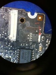
I have 2 Macbook Pro from 2009 which are not charging.i found a test point that Diadora had mentioned. that we should have 18.5 v otherwise we need to replace the DC-in, i have 0v on that point and it did not help me to replace the DC-in.
Thanks for advices.

By the way the board workes with charged battery.
 

Attachments

  • MBP_magsafe.jpg
    MBP_magsafe.jpg
    19.8 KB · Views: 2,099
Another success A1278 820-2530-A K24

Hi, fixed another one. This time it is a A1278 K24 logic board. Fault symptoms were no power via magsafe (green led off) and no power via battery. After a lengthy investigation, I found i had lost the signal SMC_PM_G2_EN to pin#13 of U7200. Funny thing is though the IC appeared to be working because I was getting 3.3v at L7220 (U7200 provides the main 3v and 5v to the rest of the board). I traced the signal back to R7273. On one side of the resistor i measured 3.2v (logic high) so I knew the signal SMC_PM_G2_EN was working ok but when i measure the otherside of the resister i got 0v. On a working logic board it should be 3.2v on both sides of the resistor. I checked to see if the U7200 was pulling the signal to ground and after checking the reading on a good board, it should read 'OL' on the meter. On mine (set to continuity check) it read 187 so I knew i had a problem with the IC. I replaced the IC with one from a scrapped board and it was working, 3.2v was now getting to pin#13 of U7200. I connected the magsafe but still no green led so it appeared there was another fault on the board. I removed th magsafe, connected the battery and fan and powered up the board, the fan started spinning, so i knew i had got a partial working board now so again, like with another board i fixed, U7200 was preventing the board from powering on.

Now to tackle the magsafe green led problem. I checked the incoming signals on U6901 and both were present. Followed the output to U6900 where I found i was not getting SYS_ONEWIRE. This one had me stumped at first because I knew the board fully worked with the battery, it just would not work with the magsafe. SYS_ONEWIRE goes directly to the SMC chip which is a BGA so i had visions of one of the solder balls underneath the chip not making contact. Before i decided to think about reflowing (never reflowed a SMC before) I took one last look around U6900 and compared to with a working board and i noticed the faulty board had a part missing. Turns out the part missing was R6929. I added a replacement and low and behold, the green led on the magsafe came on. I therefore plugged everything back together, powered on, it worked, battery charges (orange led on magsafe), heard the boot chimes and saw the flashing icon on the lcd, another sucess.

I've included some logic board pictures and schematics to show where the faults were. Thought it would make life easier for those who wish to fault find on their K24 board.

attachment.php

attachment.php

attachment.php

attachment.php
 

Attachments

  • R6929_SYS_ONEWIRE.bmp
    900.1 KB · Views: 3,507
  • R7273_SMC_PM_G2_EN.bmp
    900.1 KB · Views: 4,709
  • R7273_SCHEMATIC.bmp
    2.2 MB · Views: 4,217
  • SYS_ONEWIRE.bmp
    2.2 MB · Views: 5,524
Last edited:
Wow, I feel a bit silly now. I haven't thought of the battieries in the multimeter at all, good one!
I've replaced them and I read 3.4V (3.39V) at G3Hot and ~16.8V at DCIN.
I think I have to measure everything all over again now.

Congratulations on your successful repair, though.

EDIT #1: Currently I'm measuring some voltages on the logic board,
which is connected the MagSafe board and nothing else. The board
is not powered on but the power supply is connected (dim green light).

G3Hot is between 3.38 and 3.39V. This seems to be in the error margin
but I'm not sure. Does it have to be exactly 3.425V?

ALL_SYS_PWRGD is logically 0, so is CPUIMVP_PGOOD.
SMC_RESET_L is logically 1 (~3.3V).

All always-on (G3Hot) lanes report the right(?) voltages:

- PPBUS_G3H (12.3V)
- PPVRTC_G3H (3.27V)
- PP3V42_G3H (3.38V)
- PPDCIN_G3H (16.79V)
- PPBUS_S5_HS_OTHER_ISNS (12.3V)
- PPBUS_S5_HS_COMPUTING_ISNS (12.3V) (measured at C7331)

Except for PPVIN_SW_T29BST which should be 12.8V but really
is 0.0V. The gate of Q3880 (T29BST_PWREN_DIV_L)
measures 11.81V and PPBUS_G3H is at 12.3V. Is this correct?

What you have measured is correct. I have just checked the values with a K90i board i have here. You wont get anything on the Drain of Q3880 because the board needs to be powered on for the gate to work properly.

Forget the bypass method for the moment, with the fan, keyboard and battery connected, does the board power on, you should see the fan spinning. If not then the SMC is not functioning properly which would indicate you either have a faulty SMC or one of the core voltages that supplies either the SMC or some components that feed into the SMC i missing. If you look at one of my earlier posts for the same board as yours, you will notice the chip that supplies the main 3v/5v to the whole board was faulty. Could your board have the same fault?
 
Wow, if you have A1278 / K90i 13" water damaged no POST/BOOT than we might have the same laptop with the same symptoms.

What voltages are you measuring on U7400-19 and U7400-10?

Mine are both 0V instead of 3.3V and 1.1V which means no power to CPU and GFX = no post.

CPUIMVP_PGOOD (U7400-19): 0.08V
CPUIMVP_AXG_PGOOD (U7400-10): 0.00V - 0.01V

These signals are generated by U7400 which has currently no input voltage
on VCC (pin 40). I measured at R7462 about 0.01V. The responsible supply
lane is labeled 'P5V_S0_CPUIMVP_VDD'. The _S0 suffix and
the fact that this IC generates _PGOOD signals are reason enough to
believe that it is indeed required to boot and that something's wrong
with the power supply for this chip.

EDIT #1: Measuring PP5V_S0 at C7402 gives me 0.01V as well.

EDIT #2: Traced PP5V_S0 back to Q7860, whose drain PP5V_S0 is.
Both the source (PP5V_S3) and the gate (P5V0S0_SS) measure 0V,
which seems to be the reason for PP5V_S0 being low.

EDIT #3: If I get the table on page 73 of the spec and the previous
comments in this thread right, _Sn denotes the run state. While
S0 means running, S3 means deep sleep and G3Hot is the circuitry
that is always on (hot, hence the name). Therefore I suspect that
all before the S0 lanes receive any power, S5 and S3 have to be
powered. Right?

EDIT #4: I traced back PP5V_S3 and ended at U7200. It expects
P5VS3_EN_L to be low (therefore the _L suffix) to produce 5V.
However, P5VS3_EN_L is 3.3V and therefore high. I bridged
C7913 with a 2kOhm resistor to pull P5VS3_EN_L low and U7200
produced the said voltage. So I guess there's something wrong
with pulling P5VS3_EN_L low.
P3V3S5_EN_L is already low and
PP3V3_S5 as well as PP5V_S5 are measuring the right voltage
(3.3V and 5V respectively).

-----------------------

What you have measured is correct. I have just checked the values with a K90i board i have here. You wont get anything on the Drain of Q3880 because the board needs to be powered on for the gate to work properly.

Forget the bypass method for the moment, with the fan, keyboard and battery connected, does the board power on, you should see the fan spinning. If not then the SMC is not functioning properly which would indicate you either have a faulty SMC or one of the core voltages that supplies either the SMC or some components that feed into the SMC i missing. If you look at one of my earlier posts for the same board as yours, you will notice the chip that supplies the main 3v/5v to the whole board was faulty. Could your board have the same fault?

I don't think the SMC is broken. I just wanted to measure some components
around the SMC, plugged in the magsafe and got a bright green light for
no apparent reason. After reconnecting it, it was dim again.
Reconnecting again, it was green and faded to dim green (I've read
a post regarding this issue here somewhere).

I will test the whole package and see if the backlight now works as well.
If it does, there's 'just' the guess work to be done, which part acts weird.

EDIT #1: It's also charging correctly. The battery LEDs are right as well.
The last thing I remember doing (which has some significance in my opinion)
is that I cleaned the clock chip (U2800) from some leftover sticky-stuff.
I doubt that this is the reason though.

EDIT #2: The battery charged (all battery status LEDs light up) but the magsafe
didn't turn green. This might be a coincidence. However the starting behavior
changed:

- Battery plugged in => Turns on immediately when MagSafe is plugged in => Dim green light
- Battery not plugged in => Does nothing => Dim green light
- Pressing power on battery => Does nothing

When on battery, G3Hot is far too low (0.53V). I suspect U7000 but I'm not sure yet.
Going to do some measurements there.
 
Last edited:
CPUIMVP_PGOOD (U7400-19): 0.08V
CPUIMVP_AXG_PGOOD (U7400-10): 0.00V - 0.01V

These signals are generated by U7400 which has currently no input voltage
on VCC (pin 40). I measured at R7462 about 0.01V. The responsible supply
lane is labeled 'P5V_S0_CPUIMVP_VDD'. The _S0 suffix and
the fact that this IC generates _PGOOD signals are reason enough to
believe that it is indeed required to boot and that something's wrong
with the power supply for this chip.

EDIT #1: Measuring PP5V_S0 at C7402 gives me 0.01V as well.

EDIT #2: Traced PP5V_S0 back to Q7860, whose drain PP5V_S0 is.
Both the source (PP5V_S3) and the gate (P5V0S0_SS) measure 0V,
which seems to be the reason for PP5V_S0 being low.

EDIT #3: If I get the table on page 73 of the spec and the previous
comments in this thread right, _Sn denotes the run state. While
S0 means running, S3 means deep sleep and G3Hot is the circuitry
that is always on (hot, hence the name). Therefore I suspect that
all before the S0 lanes receive any power, S5 and S3 have to be
powered. Right?

EDIT #4: I traced back PP5V_S3 and ended at U7200. It expects
P5VS3_EN_L to be low (therefore the _L suffix) to produce 5V.
However, P5VS3_EN_L is 3.3V and therefore high. I bridged
C7913 with a 2kOhm resistor to pull P5VS3_EN_L low and U7200
produced the said voltage. So I guess there's something wrong
with pulling P5VS3_EN_L low.
P3V3S5_EN_L is already low and
PP3V3_S5 as well as PP5V_S5 are measuring the right voltage
(3.3V and 5V respectively).

Aha...I got the same measurements as you.


CPUIMVP_PGOOD (U7400-19): 0.08V
CPUIMVP_AXG_PGOOD (U7400-10): 0.00V - 0.01V

But my case it little bit better because my IC U7400 is getting power of 5V

I got the feeling that if all the power voltages are fine but only these two signals CPUIMVP_PGOOD and CPUIMVP_AXG_PGOOD are 0V I believe the IC is simply bad. I wish I had a scope and do more complex troubleshooting of the chip itself like cmdrdata mentioned before.

If I was you, I would first try to restore the power to U7400, once restored you still have a chance that Pins 19 and 10 might have the correct voltages.

If you will bring it to 5V and still Pins 19 and 10 will have 0V than we will be really on the same boat.
 
Hello again

I tried to replace the charge IC, and now i can charge the battery and the charger LED became green at the first and then orange.and charged the battery but now when i turn on the mac, the fan and harddisk, CDrom all starts but the lcd is only black i get nothing and not on the external lcd.

could you give me som advices please.

Thanks
 
CPUIMVP_PGOOD (U7400-19): 0.08V
CPUIMVP_AXG_PGOOD (U7400-10): 0.00V - 0.01V

These signals are generated by U7400 which has currently no input voltage
on VCC (pin 40). I measured at R7462 about 0.01V. The responsible supply
lane is labeled 'P5V_S0_CPUIMVP_VDD'. The _S0 suffix and
the fact that this IC generates _PGOOD signals are reason enough to
believe that it is indeed required to boot and that something's wrong
with the power supply for this chip.

EDIT #1: Measuring PP5V_S0 at C7402 gives me 0.01V as well.

EDIT #2: Traced PP5V_S0 back to Q7860, whose drain PP5V_S0 is.
Both the source (PP5V_S3) and the gate (P5V0S0_SS) measure 0V,
which seems to be the reason for PP5V_S0 being low.

EDIT #3: If I get the table on page 73 of the spec and the previous
comments in this thread right, _Sn denotes the run state. While
S0 means running, S3 means deep sleep and G3Hot is the circuitry
that is always on (hot, hence the name). Therefore I suspect that
all before the S0 lanes receive any power, S5 and S3 have to be
powered. Right?

EDIT #4: I traced back PP5V_S3 and ended at U7200. It expects
P5VS3_EN_L to be low (therefore the _L suffix) to produce 5V.
However, P5VS3_EN_L is 3.3V and therefore high. I bridged
C7913 with a 2kOhm resistor to pull P5VS3_EN_L low and U7200
produced the said voltage. So I guess there's something wrong
with pulling P5VS3_EN_L low.
P3V3S5_EN_L is already low and
PP3V3_S5 as well as PP5V_S5 are measuring the right voltage
(3.3V and 5V respectively).

Aha...I got the same measurements as you.


CPUIMVP_PGOOD (U7400-19): 0.08V
CPUIMVP_AXG_PGOOD (U7400-10): 0.00V - 0.01V

But my case it little bit better because my IC U7400 is getting power of 5V

I got the feeling that if all the power voltages are fine but only these two signals CPUIMVP_PGOOD and CPUIMVP_AXG_PGOOD are 0V I believe the IC is simply bad. I wish I had a scope and do more complex troubleshooting of the chip itself like cmdrdata mentioned before.

If I was you, I would first try to restore the power to U7400, once restored you still have a chance that Pins 19 and 10 might have the correct voltages.

If you will bring it to 5V and still Pins 19 and 10 will have 0V than we will be really on the same boat.

Did you measure the other pins on the chip? For example if CPUIMVP_VR_ON
is high? Otherwise U7400 won't do anything. See page 21 and 22 of the MAX17511 spec.

The spec also says that PGOOD needs to be pulled up, so it would be
interesting whether R2850 carries 3.3V or not. If it doesn't, you have
a problem with PP3V3_S0 and U7400 may be fine.

Regarding CPUIMVP_AXG_PGOOD I'm not sure whether this signal
is processed at all. The only reference in the spec I have here is
on sheet 73 and there the signal simply leads to an unallocated resistor
slot.

Very good point, I like the way you want to narrow it down :)

I measured the most critical/important signals like the two you mentioned. I can measure the rest, I'm just thinking if that would change anything since the INing signals are all good and the output for PGOOD is bad.

What other signal (any of the 40 pins) can have direct impact on regulating CPUIMVP_AXG_PGOOD?

My R2850 carries 3.3V and has 1k which is all good. Also, my CPUIMVP_VR_ON has 3.3V which is correct.

So it appears the IC is getting power of 5V and getting VR_ON with 3.3V but CPUIMVP_PGOOD still outputs 0V. Open-Drain Power-Good Output for Regulator A and B is crucial. These signals are forced low in shutdown (EN = GND) and/or any fault condition is detected on either regulator.

Are you agree with me that given the values measured it appears the IC is bad?
 
Last edited:
Very good point, I like the way you want to narrow it down :)

I measured the most critical/important signals like the two you mentioned. I can measure the rest, I'm just thinking if that would change anything since the INing signals are all good and the output for PGOOD is bad.

What other signal (any of the 40 pins) can have direct impact on regulating CPUIMVP_AXG_PGOOD?

My R2850 carries 3.3V and has 1k which is all good. Also, my CPUIMVP_VR_ON has 3.3V which is correct.

So it appears the IC is getting power of 5V and getting VR_ON with 3.3V but CPUIMVP_PGOOD still outputs 0V. Open-Drain Power-Good Output for Regulator A and B is crucial. These signals are forced low in shutdown (EN = GND) and/or any fault condition is detected on either regulator.

Are you agree with me that given the values measured it appears the IC is bad?

Well, you should check the voltage of CPUIMVP_FBA, which is the pin on
which U7400 senses the output voltage (FeedBack A). If it is low or not
the correct voltage, POKA (Power OK A) will not be L1.

What other signal (any of the 40 pins) can have direct impact on regulating CPUIMVP_AXG_PGOOD?

For AXG_PGOOD this would be FBB (FeedBack B). As I said, this signal does not seem to be
evaluated so I would focus on CPUIMVP_PGOOD.
 
Last edited:
Well, you should check the voltage of CPUIMVP_FBA, which is the pin on
which U7400 senses the output voltage (FeedBack A). If it is low or not
the correct voltage, POKA (Power OK A) will not be L1.


For AXG_PGOOD this would be FBB (FeedBack B). As I said, this signal does not seem to be
evaluated so I would focus on CPUIMVP_PGOOD.

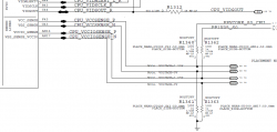
My signal CPUIMVP_FBA which traces back to CPU_VCCSENSE_P comes directly from CPU chipset. It is reading 0V which should be 1.1V, but if you look at my picture attached CPU_VCCSENSE is just a sense line which reads the voltage from PPVCORE_S0_CPU --this is my main issue. I should get 1.1V instead of 0V.

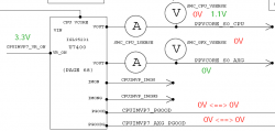
Now, if you look at my other picture the signal PPVCORE_S0_CPU comes from U7400....so going in circles we are back at square one.

Note: I already checked R7412 which has 8.4k as well as R7422 (8.6k)
 

Attachments

  • Capture33.PNG
    Capture33.PNG
    55.9 KB · Views: 683
  • Capture34.PNG
    Capture34.PNG
    28.3 KB · Views: 770
Last edited:
My signal CPUIMVP_FBA which traces back to CPU_VCCSENSE_P comes directly from CPU chipset. It is reading 0V which should be 1.1V

Note: I already checked R7412 which has 8.4k as well as R7422 (8.6k)

Well, this means that either the feedback cable is broken /
shorted to ground or the power from U7400 does not reach the CPU.

Out of pure interest regarding my board: the PGOOD voltages
from U7400 have to be set when only the magsafe is connected
and the computer is waiting to be powered on? The logic shown
in the schematics, as I understand it, tells quite the opposite.

On battery only
CPUIMVP_PGOOD - 0V
CPUIMVP_AXG_PGOOD -0V

On Megsafe only or with battery (computer on)
CPUIMVP_AXG_PGOOD -1.1V
CPUIMVP_PGOOD - 3.3V

So did you make any progress with your board?
 
Register on MacRumors! This sidebar will go away, and you'll see fewer ads.