Become a MacRumors Supporter for $50/year with no ads, ability to filter front page stories, and private forums.
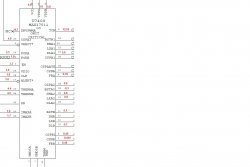
My signal CPUIMVP_FBA which traces back to CPU_VCCSENSE_P comes directly from CPU chipset. It is reading 0V which should be 1.1V, but if you look at my picture attached CPU_VCCSENSE is just a sense line which reads the voltage from PPVCORE_S0_CPU --this is my main issue. I should get 1.1V instead of 0V.

Now, if you look at my other picture the signal PPVCORE_S0_CPU comes from U7400....so going in circles we are back at square one.

Note: I already checked R7412 which has 8.4k as well as R7422 (8.6k)

I hope I understood the situation correctly:

- You have no outgoing power on U7400 to the CPU (vcore)

If that's correct, then the U7400 seems to be faulty. Because
everything seems to be in order around U7400.

Please correct me if I didn't understand your situation correctly.

On battery only
CPUIMVP_PGOOD - 0V
CPUIMVP_AXG_PGOOD -0V

On Megsafe only or with battery (computer on)
CPUIMVP_AXG_PGOOD -1.1V
CPUIMVP_PGOOD - 3.3V

So did you make any progress with your board?

No. I still don't know whether or not PP3V3_S0 and friends
are vital for the MagSafe LED to turn green or not.
I'm also not sure which components can influence the
MagSafe LED at all. If it is just the SMC then I think
that PP3V3_S0 is indeed important. But I'm simply
not sure about that. Any help is appreciated.

EDIT #1: I'm still measuring 0.09V on PP3V3_S0
directly at the FET that is supposed to feed it from
PP3V3_S5 (Q7830). P3V3S0_SS (gate voltage) is at
3.3V.
 
Last edited:
I hope I understood the situation correctly:

- You have no outgoing power on U7400 to the CPU (vcore)

If that's correct, then the U7400 seems to be faulty. Because
everything seems to be in order around U7400.

Please correct me if I didn't understand your situation correctly.


No. I still don't know whether or not PP3V3_S0 and friends
are vital for the MagSafe LED to turn green or not.
I'm also not sure which components can influence the
MagSafe LED at all. If it is just the SMC then I think
that PP3V3_S0 is indeed important. But I'm simply
not sure about that. Any help is appreciated.

EDIT #1: I'm still measuring 0.09V on PP3V3_S0
directly at the FET that is supposed to feed it from
PP3V3_S5 (Q7830). P3V3S0_SS (gate voltage) is at
3.3V.

Here are my voltages (Megsafe), compare to yours.

Q7830
S-D (1.9k)
S-G-D (100k)

S-D (3.3V)
G (0V)
 
Last edited:
I hope I understood the situation correctly:

- You have no outgoing power on U7400 to the CPU (vcore)

If that's correct, then the U7400 seems to be faulty. Because
everything seems to be in order around U7400.

Please correct me if I didn't understand your situation correctly.


No. I still don't know whether or not PP3V3_S0 and friends
are vital for the MagSafe LED to turn green or not.
I'm also not sure which components can influence the
MagSafe LED at all. If it is just the SMC then I think
that PP3V3_S0 is indeed important. But I'm simply
not sure about that. Any help is appreciated.

EDIT #1: I'm still measuring 0.09V on PP3V3_S0
directly at the FET that is supposed to feed it from
PP3V3_S5 (Q7830). P3V3S0_SS (gate voltage) is at
3.3V.

For the magsafe led to go green you need these 3 main signals to be present
PP3V42_G3H - 3.42v U6901 pin#5
SMC_BC_ACOK - 3.2v U6901 Pin#1&2
SYS_ONEWIRE - 3.2v U6900 pin#14

PP3V42_G3H is what's commonly referred to as 'G3 HOT' and can be measured at L6995. The SMC needs to see various signals which spur off PP3V42_G3H. Goto page 46 and you will see that the SMC needs to see 3.42v at various different points, SMC_ONOFF_L,G3_POWERON_L and so on. This is where SYS_ONEWiRE is produced so without those initial signals coming in from PP3V42_GH, the SMC would never produce SYS_ONWIRE.

SMC_BC_ACOK is produced by the charger chip U7000 pin#14 so you need to make sure the voltage supply to the chip is present.

There is an excellent document in this thread somewhere titled 'A1286 power sequence'. I have used this document on numerous occasions to solve magsafe led problems and power on problems. Some of the signal id labels might be slightly different but they still do the same job.
 
Can anybody chime in on this... I have a mid 09 macbook logic board that will only power on with the battery. but the magsafe will still turn green when plugged in but once i plug the charger with the battery connected the light on the side will blink as if it was charging but refuse to charge. I did the ADS on it and it passes everything.. All the fuses are good and the power block are recieving power. Please help cmdrdata, dadioh, laptech or anybody else to help me fix this issue.
 
Hi, fixed another one. This time it is a A1278 K24 logic board. Fault symptoms were no power via magsafe (green led off) and no power via battery. After a lengthy investigation, I found i had lost the signal SMC_PM_G2_EN to pin#13 of U7200. Funny thing is though the IC appeared to be working because I was getting 3.3v at L7220 (U7200 provides the main 3v and 5v to the rest of the board). I traced the signal back to R7273. On one side of the resistor i measured 3.2v (logic high) so I knew the signal SMC_PM_G2_EN was working ok but when i measure the otherside of the resister i got 0v. On a working logic board it should be 3.2v on both sides of the resistor. I checked to see if the U7200 was pulling the signal to ground and after checking the reading on a good board, it should read 'OL' on the meter. On mine (set to continuity check) it read 187 so I knew i had a problem with the IC. I replaced the IC with one from a scrapped board and it was working, 3.2v was now getting to pin#13 of U7200. I connected the magsafe but still no green led so it appeared there was another fault on the board. I removed th magsafe, connected the battery and fan and powered up the board, the fan started spinning, so i knew i had got a partial working board now so again, like with another board i fixed, U7200 was preventing the board from powering on.

Now to tackle the magsafe green led problem. I checked the incoming signals on U6901 and both were present. Followed the output to U6900 where I found i was not getting SYS_ONEWIRE. This one had me stumped at first because I knew the board fully worked with the battery, it just would not work with the magsafe. SYS_ONEWIRE goes directly to the SMC chip which is a BGA so i had visions of one of the solder balls underneath the chip not making contact. Before i decided to think about reflowing (never reflowed a SMC before) I took one last look around U6900 and compared to with a working board and i noticed the faulty board had a part missing. Turns out the part missing was R6929. I added a replacement and low and behold, the green led on the magsafe came on. I therefore plugged everything back together, powered on, it worked, battery charges (orange led on magsafe), heard the boot chimes and saw the flashing icon on the lcd, another sucess.

I've included some logic board pictures and schematics to show where the faults were. Thought it would make life easier for those who wish to fault find on their K24 board.

Image
Image
Image
Image

I see you were able to fix a quite few LB which is awesome and thanks for sharing your stories. My issue here is the continuation of what I posted here recently. So I discovered a short on line(s) PPBUS_S5_HS_COMPUTING_ISNS

This line connects on R5400 with PPBus_G3H, so I had my short pretty much all the way to the battery connector. Having such a big range I narrowed it down and removed R5400. The short before F7040 disappeared but was present going forward of R5400 to (U7600, U7400, U7300, U7100)

This signal connects to 42 components (I counted manually) which means any of these 42 mostly capacitors and FETS might have a short. But how to further narrow it down? I'm sure there is another way than removing these components one by one.

Your situation with U7200 and the resistor pulling to ground is similar to mine ( please look at the second picture attached) the difference is that in your case the side going towards IC was pulling to ground the other was fine. Which means your IC was fault here. My case is opposite, pin 2 of R7402 is shorted to ground which carries our signal PPBUS_S5_HS_COMPUTING_ISNS which in turn connects to other 41 components.

Note: (all of these components are capacitors and FETS only except R7402 which when measured directly pin1+2 had 90k)

I appreciate your help.
 

Attachments

  • short.PNG
    short.PNG
    34 KB · Views: 1,011
  • short2.PNG
    short2.PNG
    60 KB · Views: 1,135
Last edited:
I see you were able to fix a quite few LB which is awesome and thanks for sharing your stories. My issue here is the continuation of what I posted here recently. So I discovered a short on line(s) PPBUS_S5_HS_COMPUTING_ISNS

This line connects on R5400 with PPBus_G3H, so I had my short pretty much all the way to the battery connector. Having such a big range I narrowed it down and removed R5400. The short before F7040 disappeared but was present going forward of R5400 to (U7600, U7400, U7300, U7100)

This signal connects to 42 components (I counted manually) which means any of these 42 mostly capacitors and FETS might have a short. But how to further narrow it down? I'm sure there is another way than removing these components one by one.

Your situation with U7200 and the resistor pulling to ground is similar to mine ( please look at the second picture attached) the difference is that in your case the side going towards IC was pulling to ground the other was fine. Which means your IC was fault here. My case is opposite, pin 2 of R7402 is shorted to ground which carries our signal PPBUS_S5_HS_COMPUTING_ISNS which in turn connects to other 41 components.

Note: (all of these components are capacitors and FETS only except R7402 which when measured directly pin1+2 had 90k)

I appreciate your help.

PPBUS is the primary 12v source that is then down regulated to various voltages to needed by various components. Notice that to do this, for every voltage needed, it is usually routed thru a pair of power FETs that have their GATEs pulsed to achieve the target DC voltage. So if you remove the respective FET you may be able to narrow down where the "short" is at. However, you have to be sure that it is a "short". Remember that this is the main power, so it will have a low impedance (meaning high current load) to begin with.

On another subject, if the magsafe circuitry and LED status is working, battery is charging and 12v measured at the fuse (e.g., F7040), then remaining power up problem is in my opinion is no longer a magsafe issue as mentioned in the past few posts.

My short to ground discovery started with measuring voltages. I was in pretty good shape before, my issue was only around VCore Regular (U7400) my CPUIMVP_PGOOD was logic 0. So while I was waiting for the IC replacement, I decided to reflow it. That didn't make any difference so I decided to remove it clean it and re-solder it. Another thing that I did was put a new R7402 (100K) as the old one looked burned and once I took it off, the left side came off, so I need it is time for new resistor. The problem was that I didn't have any 90.9K at hand so I used 100K also 402 package. After that my voltages were off. R7402-2 had 3.3V instead of 12.5V and even my F7040 had 1.8V instead of 12.5

I traced the power and discovered where the short was. I'm pretty much sure if I locate the component that is pulling to ground my voltages will at least come back to the state before I touched U7400.

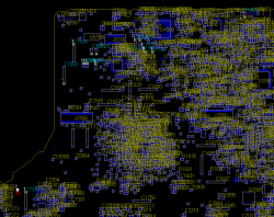
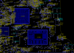
Below is the top and the bottom with all component effected (total 42) because they are all connected via our signal [PPBUS_S5_HS_COMPUTING_ISNS] they are all shorted to ground. If they were resistors it would be easier to measure at least the resistance which would give us some smoking guns but measuring capacitors in-circuit is different.
 

Attachments

  • short_top.PNG
    short_top.PNG
    79 KB · Views: 1,003
  • short_btm.PNG
    short_btm.PNG
    66.2 KB · Views: 1,072
Last edited:
Can anybody chime in on this... I have a mid 09 macbook logic board that will only power on with the battery. but the magsafe will still turn green when plugged in but once i plug the charger with the battery connected the light on the side will blink as if it was charging but refuse to charge. I did the ADS on it and it passes everything.. All the fuses are good and the power block are recieving power. Please help cmdrdata, dadioh, laptech or anybody else to help me fix this issue.

If the system works on battery then everything pass F7000 (for mid 2009) is most likely ok. You need to make sure that G3HOT is 3.4v when only magsafe is plugged in (with no battery, the plug should be green). If you have G3HOT, then check for 12v at F7000 (both side) with no battery. If you have 12+v at that fuse, and the battery is plugged in, then check Q7055. If the gate is near 12v or 0v, then that would be the reason your battery is not charging. That FET must be ON for charging to take place.
 
I see you were able to fix a quite few LB which is awesome and thanks for sharing your stories. My issue here is the continuation of what I posted here recently. So I discovered a short on line(s) PPBUS_S5_HS_COMPUTING_ISNS

This line connects on R5400 with PPBus_G3H, so I had my short pretty much all the way to the battery connector. Having such a big range I narrowed it down and removed R5400. The short before F7040 disappeared but was present going forward of R5400 to (U7600, U7400, U7300, U7100)

This signal connects to 42 components (I counted manually) which means any of these 42 mostly capacitors and FETS might have a short. But how to further narrow it down? I'm sure there is another way than removing these components one by one.

Your situation with U7200 and the resistor pulling to ground is similar to mine ( please look at the second picture attached) the difference is that in your case the side going towards IC was pulling to ground the other was fine. Which means your IC was fault here. My case is opposite, pin 2 of R7402 is shorted to ground which carries our signal PPBUS_S5_HS_COMPUTING_ISNS which in turn connects to other 41 components.

Note: (all of these components are capacitors and FETS only except R7402 which when measured directly pin1+2 had 90k)

I appreciate your help.

Looking at your diagram, I would remove U5400 as this connects directly to PPBUS_S5_HS_COMPUTING_ISNS via pin#5. It is possible this chip has an internal short and is linking pin#5 & pin#2 together. Once removed, if the short is gone, you have found problem with U5410 BUT if short still exists then I am afraid you will have to remove each component one by one to find which one is causing the short. It takes ages, I've had to remove 64 components on a board to find a short and it is not something I want to do again.
 
Looking at your diagram, I would remove U5400 as this connects directly to PPBUS_S5_HS_COMPUTING_ISNS via pin#5. It is possible this chip has an internal short and is linking pin#5 & pin#2 together. Once removed, if the short is gone, you have found problem with U5410 BUT if short still exists then I am afraid you will have to remove each component one by one to find which one is causing the short. It takes ages, I've had to remove 64 components on a board to find a short and it is not something I want to do again.

All the pins on U5400 have high impedance in K or Mohms, except pin1 and 2 which is GRD. pin#5 was shorted to ground before I removed R5400 which acts as a link between what is before and after it. If you remove R5400 you will see 4 pads. My short is ONLY on pad 2 which is PPBUS_S5_HS_COMPUTING_ISNS which now after R5400 removed does not connects directly to U5400. This is how far I was able to narrow it down, but from here I have no idea how I can cut the troubleshooting from 42 component to at least half. I was afraid what I was considering and now you confirmed is true. Remove it one-by-one....

If you or anybody will just think of a way to narrow it down please let me know.
 
Last edited:
If the system works on battery then everything pass F7000 (for mid 2009) is most likely ok. You need to make sure that G3HOT is 3.4v when only magsafe is plugged in (with no battery, the plug should be green). If you have G3HOT, then check for 12v at F7000 (both side) with no battery. If you have 12+v at that fuse, and the battery is plugged in, then check Q7055. If the gate is near 12v or 0v, then that would be the reason your battery is not charging. That FET must be ON for charging to take place.

MY g3hot is 3.38 below is what i have measured so far where would the gate be at?
 
MBP 13" not starting despite SMC bypass no green Magsafe Led

I have a mid 2009 MBP 13" that won't start either on AC or battery power using the SMC bypass.
It had a little liquid spill that I cleaned off.
The Magsafe LED is going neither green nor orange.
G3Hot is good, I have 16,9V on both sides of the fuse near the DC in connector, but nothing on the main fuse unless a battery is connected.
With battery there are 11,5V on both sides of the main fuse.
On the mosfet near the LVDS connector I have with AC+battery 11,17V on the source, 11,06 on the gate and 0,3V on the drain.
Unplugging the battery, the source voltage drops slowly.
On the mosfet near the DC in I have 16,9V on the source, 16,75 V on the gate and 0,3V on the drain.

Any Idea what could be wrong?
 
For the magsafe led to go green you need these 3 main signals to be present
PP3V42_G3H - 3.42v U6901 pin#5
SMC_BC_ACOK - 3.2v U6901 Pin#1&2
SYS_ONEWIRE - 3.2v U6900 pin#14

PP3V42_G3H is what's commonly referred to as 'G3 HOT' and can be measured at L6995. The SMC needs to see various signals which spur off PP3V42_G3H. Goto page 46 and you will see that the SMC needs to see 3.42v at various different points, SMC_ONOFF_L,G3_POWERON_L and so on. This is where SYS_ONEWiRE is produced so without those initial signals coming in from PP3V42_GH, the SMC would never produce SYS_ONWIRE.

SMC_BC_ACOK is produced by the charger chip U7000 pin#14 so you need to make sure the voltage supply to the chip is present.

There is an excellent document in this thread somewhere titled 'A1286 power sequence'. I have used this document on numerous occasions to solve magsafe led problems and power on problems. Some of the signal id labels might be slightly different but they still do the same job.

All those requirements are met, PP3V42_G3H and SMC_BC_ACOK,
measured somewhere in the network and specifically on the probes, are OK.
I also measured the voltages of the wires shown on page 46. All but
G3_POWERON_L, which measures 0.01V, measure voltages around 3.4V
so those seem to be OK as well.

I noticed that SMC_RESET_L is high. Does SMC_RESET_L need to be
low all the time? Or just for a brief moment? Currently,
SMC_RESET_L is high all the time after I plug in the magsafe adapter.

Sadly, I couldn't find the document you mentioned. I would greatly
appreciate a link.

My measurements so far:

Logically

- ALL_SYS_PWRGD: 0 should be 1
- CPUIMVP_PGOOD: 0 should be 1
- SMC_BC_ACOK: 1
- SMC_RESET_L: 1 should be 0?
- P5V3V3_PGOOD: 0 should be 1
- P5VS3_ENTRIP: 0 should be 1
- P5VS3_EN_L: 1 should be 0
- P5VS5_EN_L: 0
- PM_SLP_S4_L: 0
- P5V3V3_REG_EN: 1
- SMC_ONOFF_L: 1

`_L` means an inverted signal (L for low).
The signal is expected to be low, so logically false.

`_EN` is short for `_ENABLE`.

`_PGOOD` is short for `_POWER_GOOD`.

Voltages

- PPDCIN_G3H: 16.5V (16.76V)
- PP3V42_G3H: 3.42V (3.37V)
- PPBUS_G3H: 12.5V (12.4V)
- PPBUS_S5_HS_OTHER_ISNS: 12.5V (12.4V)
- PP5V_S5: 5V (4.9V)
- PP3V3_S5: 3.3V (3.26V)
- PP5V_S3: Wrong: 0V (should be 5V)
- PP1V5_S3: Wrong: 0V (depends on PP5V_S3, should be 1.5V)
- PP3V3_S0: Wrong: 0.09V (should be 3.3V)
- DCIN_S5_VSENSE: 16.5V
- SMC_DCIN_VSENSE: 3.3V at 19.77V input (2.81V at 16.76V input)

When on occasion the magsafe is brightly green (still no clue when
this happens; still suspecting a bad cap somewhere) the voltage
on PP5V_S3 is good.

EDIT #1: For some reason the magsafe now refuses to go dim-green
and stays bright green all the time. Also the computer successfully
POSTS now all the time. While this is generally a good thing it makes it
impossible for me to figure out what the actual problem was.

The only notable difference I could see is that the PP*V_S3 and S0
lines are working properly now and that ADAPTER_SENSE is now
reporting the same voltage as SYS_ONEWIRE instead of ~10V.

However, some problems are still left:
- Booting from battery does not work
- The backlight does not work

Regarding the backlight:
- Supply voltages are OK:
  • PPBUS_SW_BKL: 12.5V
  • PP5V_S0: 5V
- PPVOUT_SW_LCDBKLT_FB: 12.5V
- PPBUS_SW_LCDBKLT_PWR_SW: 12.5V
- PPVOUT_SW_LCDBKLT: 12.5V instead of ~25V.

Currently I suspect that the clock signal to U9701 or U9701 itself is broken.
PPBUS_SW_LCDBKLT_PWR_SW needs to be pulled to ground periodically so that
L9701 and friends can act as a boost converter.
This seems not to be working as the output voltage is the same as the
input voltage.


Regarding the battery:
- The charging LEDs report that the battery is fully charged
- Pressing the power button doesn't do anything
- PPVBAT_G3H_CONN is supplying 12.3V

I'm still unsure how to tackle this one and will probably focus on the backlight first.
Any ideas on this one?

EDIT #2:
The backlight boost circuit does not need an external clock signal.
Page 20 of the LP8552 IC shows the internal switching circuit.
Sadly I couldn't find the LP8550 spec but the LP8552 spec is sufficient for now.

The readings around LP8550 say:

WLED Resistances:

- R9716: 90.9K
- R9714: 16.2K
- R9741: 10.0K
- R9755: 10.0K

WLED Voltages:

- FB: 12.4V
- FSET: 0V
- PWM: 3.07V
- ISET: 0V
- EN: 3.07V
- FAULT: 0V
- SW: 12.4V
- FILTER: 0V
- VLDO/VIN: 4.97V
- OUT6: 0V
- VSYNC: 0V
- OUT5: 0V
- OUT4: 0V
- OUT1: 0V
- OUT2: 0V
- OUT3: 0V

(Pin associations taken from https://forums.macrumors.com/posts/17225892/)

I suspect that either the chip is broken or the PWM value is wrong but maybe I missed something.

EDIT #3:
Stupidity knows no bounds... I accidentally shorted R7001 and C7050. Smoke and smell
and back to dim magsafe light again... I guess/hope the cap is gone and I can replace it.
I'm currently looking for a replacement.
 
Last edited:
All the pins on U5400 have high impedance in K or Mohms, except pin1 and 2 which is GRD. pin#5 was shorted to ground before I removed R5400 which acts as a link between what is before and after it. If you remove R5400 you will see 4 pads. My short is ONLY on pad 2 which is PPBUS_S5_HS_COMPUTING_ISNS which now after R5400 removed does not connects directly to U5400. This is how far I was able to narrow it down, but from here I have no idea how I can cut the troubleshooting from 42 component to at least half. I was afraid what I was considering and now you confirmed is true. Remove it one-by-one....

If you or anybody will just think of a way to narrow it down please let me know.

Just checked with a working board I have at work and you are right, removal of R5400 breaks the circuit to U5400 but the schematic contradicts this. It would therefore appear as though one of the components connected to PPBUS_S5_HS_COMPUTING_ISNS is causing the short and I am afraid it will mean the removal of each part one by one to find the culprit.
 
hi
i've got one(2009 13" 2.53) which is working only when psu is connected, is charging battery but wont start on battery only and cuts off when you unplugging cable.
g3hot on battery its only 1.24V and 3.4V when connected. Battery tested on other board and it shows 3.4V on g3hot pin. So problem may be somewhere between battery connector and g3hot?
Any suggestions ?
thanks
 
Just checked with a working board I have at work and you are right, removal of R5400 breaks the circuit to U5400 but the schematic contradicts this. It would therefore appear as though one of the components connected to PPBUS_S5_HS_COMPUTING_ISNS is causing the short and I am afraid it will mean the removal of each part one by one to find the culprit.

I know if you look at the schematic it appears as the lines are connected only it looks totally different when you look at the pads of the LB. Anyway...I made some progress...I identified the short component(s) replaced it and the board is free of shorts:) Which means I have my power back 12.5V, my computer powers either on battery or megsafe and also charges the battery.

So for those that were trying to follow my case...it took me 12 components instead of 42 to remove the short. Well 12 is better than 42! That's for sure.

After removing them, 3 of them were bad Q7100, R7147 and C7140. After waiting several days for arrival finally I solder it on and the short was gone!

Now, this brought me back to the stage were CPUIMVP_PGOOD and CPUIMVP_AXG_PGOOD were logic 0. Said that I also installed brand new
U7400. I powered it on, all the voltages were good 12.5V, 3.3V....except my CPUIMVP_PGOOD and CPUIMVP_AXG_PGOOD were STILL logic 0 :mad:

I also determines that my PPVCORE_S0_CPU signal is logic 0 as well which is one of the main voltages to debug. So, I'm really puzzled because according to the schematic my PPVCORE_S0_CPU is generated form U7400 which I already replaced....I'm going in circles here....
 
Last edited:
First off thanks to all the members who have helped me out. Very valuable information!

I'm hoping you guys can help me out with this one. I've got an a1297. It will not recognize the battery. It will also not start from the battery. One more interesting thing is, if I start from the magsafe it will continue running off of the battery after it is unplugged from the magsafe.

If anyone could point me in the right direction or tell me where to start testing it would be greatly appreciated.

I'm not the best at diagnosing things, but I do plenty of reballs & re-chips, so if anyone has any BGA questions feel free to ask:)

Make sure there are about 3.425V on the G3Hot. It seems to me that some
part is not getting enough power and therefore the computer fails to POST.

Look in the schematic and the boardview, everything that's labeled G3Hot
must have power the moment you plug in the battery.

------------------------------

My status is that I seem to have fried my U7000. As far as I understand, the IC
is fed from CHGR_DCIN and generates 5.1V to power itself. However, measuring
those voltages at R7001 gives me about 0.5V while CHGR_DCIN is at 16.5V.

How can I verify best that I need to replace U7000? Also, a hint where to get
the datasheets for the ISL6259A would be nice. Thanks!
 
Last edited:
New MBP Issue

HI guys. First time poster - overwhelmed by your genius and the 61 pgs related to this idea.

I have a late 2008 unibody MBP. 8 months ago, it had a spill. Wouldn't boot up, the guy replaced the Magsafe, and cleaned off some corrosion and replaced a fan - worked like a charm for months.

Night before last, battery running low, I shut the lid and go to bed. And it won't boot in the morning. I've tried an SMC reset (several ways in the event that I'm an idiot, could still be true) and it didn't do anything. I did a SMC bypass (from this forum) by holding the power key then plugging in the adapter without a battery, and nothing still.

I tried a PRAM reset, but that doesn't seem to do anything. It looks like I should go buy some kind of electrical tester meter and then check to see if the SMC controller works, but if that were true, wouldn't the bypass have leaped it?

Battery charged 50%, multiple power adapters, and I'm at a loss.

Would love your help. Has been the worst 24 hours on record over the last 5 years, and the computer is only 10% of it. I've got a job I'm trying to finish, past deadline, crunched finances and I can't get the computer to work. Drinking, violence, addictions would all prove pointless, but considerable options at this point, if it would solve anything...
:D Help please?
 
D6905 location?

just found block diagram for my case but no board view. i see there is diode (d6905) between G3H and battery and i think it may be a problem. But i have no idea where D6905 is.
Have someone got a board view for 820-2530 or could help me find that diode? :)
thanks
 
I know if you look at the schematic it appears as the lines are connected only it looks totally different when you look at the pads of the LB. Anyway...I made some progress...I identified the short component(s) replaced it and the board is free of shorts:) Which means I have my power back 12.5V, my computer powers either on battery or megsafe and also charges the battery.

So for those that were trying to follow my case...it took me 12 components instead of 42 to remove the short. Well 12 is better than 42! That's for sure.

After removing them, 3 of them were bad Q7100, R7147 and C7140. After waiting several days for arrival finally I solder it on and the short was gone!

Now, this brought me back to the stage were CPUIMVP_PGOOD and CPUIMVP_AXG_PGOOD were logic 0. Said that I also installed brand new
U7400. I powered it on, all the voltages were good 12.5V, 3.3V....except my CPUIMVP_PGOOD and CPUIMVP_AXG_PGOOD were STILL logic 0 :mad:

I also determines that my PPVCORE_S0_CPU signal is logic 0 as well which is one of the main voltages to debug. So, I'm really puzzled because according to the schematic my PPVCORE_S0_CPU is generated form U7400 which I already replaced....I'm going in circles here....

I've included a diagram of the voltages on U7400. The voltages were taken from a working board, hope this is of some help to you.

attachment.php
 

Attachments

  • U7400_VOLT_READINGS.jpg
    U7400_VOLT_READINGS.jpg
    83.4 KB · Views: 2,703
Last edited:
I've included a diagram of the voltages on U7400. The voltages were taken from a working board, hope this is of some help to you.

Image

Thanks laptech, I appreciate your help. I decided I will be sending this board to a shop overseas, these guys are really good, they fixed 2 other motherboards that were way beyond repair, every other shop was refusing to take it.

One LB was with broken LCVD connector and all traces around it. Some idiot thought he can starting fixing boards like this and it appears he used regular solder iron. Whatever he couldn't remove he just forced and ripped all the traces around...it was bad. This board here, I already spent too much time on it, I fixed what I could. The values from your board are of course different than on mine, but the real issue was to identify what is causing it....and that I can't figure out. This board was already in two other repair shops, they also gave up stating they can't fix it. One shop re-balled my SB, so maybe they didn't install it right, maybe I have a short on the chip or maybe the chip is bad...who knows.

There is no way for me to test the chip or replace it. I don't have equipment for that as it requires real good rework station ($10k). I fixed many boards but I guess sometimes you just can't fix it all....:(
 
Last edited:
MacBook Air A1369 wont charge

I have a macbook air A1369 that wont charge. It worked fine while there was still charge in the battery. Now it is quite dead. Plugging in the power adapter yields no effect, no lights come on, nothing. The adapter works fine on other macs... I found two fuses: one on the i/o board and one near the battery plug, both test OK.
Could someone please point me in a direction on where to start with this beast?
All help appreciated!
 
Anyway...I made some progress...I identified the short component(s) replaced it and the board is free of shorts:) Which means I have my power back 12.5V, my computer powers either on battery or megsafe and also charges the battery.

So for those that were trying to follow my case...it took me 12 components instead of 42 to remove the short. Well 12 is better than 42! That's for sure.

Congratulations on brute forcing this. I may have done the same thing 30 years ago but with the very fine geometry components nowadays I think I'm way too old!

BTW a long long time ago HP (nee Agilent) used to sell a hand held device, similar to a logic probe, that (somehow) claimed to detect current flow in PCBs, etc. Designed specifically to troubleshoot problems like yours.

http://www.home.agilent.com/en/pd-1000001462:epsg:pro-pn-547A/current-tracer?&cc=US&lc=eng

I never owned one, they were expensive. I don't know how they worked, or how well they worked. Perhaps there was a tiny hall effect device at the tip to detect current flow (a short will have high current).

Anyway, maybe there's a newer version of that device, by Agilent or someone else.
 
help with 13" a1181 T7400 MB

Hi Guys

Im new here and found this forum extremly interesting and full of helpfull posts.
I have a MB a1181 t7400 2.16 ghz i think mid or early 2007. I was using it and had to unplug the charger from the wall and plug in an extension lead then plug the charger back in. after i done this the mac went to sleep. I was unable to wake it so switched off with power button. Couldnt started up ever since. tried all the reseting procedures no avail. Te charger charges the battery cause I let the battery uncharged for few days and then magsafe turned green than to amber. Measured and getting charge voltage on dc in and on battery terminals as well. Found the G3hot(?) solder points on logic board.Measured voltage there and getting 3.3 volts there.
Macbook never been dropped nor had any liquid damage. No signs of corrosion either.
I dont really know what to do next.
I would appreciate any help from you guys.

Thank you
 
Register on MacRumors! This sidebar will go away, and you'll see fewer ads.