Become a MacRumors Supporter for $50/year with no ads, ability to filter front page stories, and private forums.
No Video/POST

Before you go the reballing route you should doublecheck the schematic to see if the signal from the Northbridge goes through a device on the logic board. Like some sort of muxing device. If it does then that could be the failure point. If the signal goes directly to the SMC then it could be the Northbridge or it could be the SMC.

I got a similar problem with my Early 2011 A1278 13" which had a liquid damage. The symptoms are no video/POST. I already had Northbridge reballed, replaced few shorted components but the issue still remains. The good thing is that the megsafe turn green then orange so it appears to be charging the battery.

After I press the power button the fans spins normally but then after 30 second it starts spinning faster all the way to the full speed. The screen remains dark/no video, no beeps when RAM removed.

I already tried the bypass method that Dadioh mentioned at the beginning of this post, but that however didn't do anything the behavior stays the same.

So at this point the video issue might point to GPU chip. I know that if during the quick self test (POST) there is an issue let's say with GPU the whole boot process will be put to a hold. But at the same time SMC chip is also responsible for many parts of communication to/from GPU so at this point I really can't tell which one would be a fault here.

My question for anybody is what other tests I can perform to roll out either one before reballing. I know there are some slot testers to check the communication between GPU but I don't have such device and never used it.

The bottom line is I don't want to reball/replace SMC if GPU would be our faulty component or vice-versa.

I want to leave the board as virgin as possible and avoid replacing the wrong components.

Any help would be greatly appreciated as this forum is literally a gold mine of electronic information that probably you won't find anywhere else.
 
Last edited:
OK, no green led on magsafe means you have a DC detection fault on the board. Using the battery be used. With RAM removed, if the NB is initial working you should hear a repeated beep tone. Usually when laptops have no memory they give out a special memory beep code indicating that the board has a memory issue. With the this logic board if the RAM is removed, the logic board should keep giving off an audiable beep and will keep doing so until you removed the power source. The crackling sound could be the memory error beep but it could be the audio section of the board is damaged by the liquid hence why the crackling instead of a clear BEEP sound. If you notice the fan spining then stop, then spin then stop, which mimics the 5 sec interval error you mentioned then it would appear you have a power supply issue somewhere on the board and when the voltage hits that faulty part, the board resets itself.

The board view and schematic for your logic board can be found in this thread. I found it while looking through the many pages.

regards Rog

My first inspection leads me to the inrush limiter.
- Only AC adapter plugged in: Q7085 DCin = 16.6 V; gate (pin 4) 15.7 V; DRAIN (5) = 0.15 V?
- + Battery: Q7080 = S (1/2/3) 12.4 V; gate = 12.3 V; DRAIN (5) = 0.15 V?
- R drain (5)/Ground = 9Mohm.

Do I now assume that Q7085/7080 are broken?
In U7000 display PIN 14 = 3.3 V.
DCIN connector shows only thin flashing LED.

Without battery, the MBP does not respond to the start button.
With Battery + MAGSAVE there is a launch attempt of 1.5 sec duration.
 

Attachments

  • Inrush.bmp
    1.6 MB · Views: 593
Last edited:
My first inspection leads me to the inrush limiter.
- Only AC adapter plugged in: Q7085 DCin = 16.6 V; gate (pin 4) 15.7 V; DRAIN (5) = 0.15 V?
- + Battery: Q7080 = S (1/2/3) 12.4 V; gate = 12.3 V; DRAIN (5) = 0.15 V?
- R drain (5)/Ground = 9Mohm.

Do I now assume that Q7085/7080 are broken?
In U7000 display PIN 14 = 3.3 V.
DCIN connector shows only thin flashing LED.

Without battery, the MBP does not respond to the start button.
With Battery + MAGSAVE there is a launch attempt of 1.5 sec duration.

Q7085 needs U7000 pin 1 to go to ~0v, and thus it will turn on and pass the 16.6v to the drain side. I suggest you look at my old post showing the U7000 internal block diagram (ISL6258). For U7000-1 to go to ground i.e., it's poen collector output FET is turned on, this chip needs to see pin 3 (ACIN) to be present (non-zero voltage, probably around 3v).
 
Picked up a liguid damaged mid 2010 13in for dirt cheap....board was cleaned. Plugged in magsafe (good dc board) and mostly get the very faint green, although did light up normally a few times....only getting around 2.5v on the g3...then disaster...had a chip light up
IMG_0121_zpse46889fa.jpg


The chip is 9563BHZ, R5400, H032BB7. Can this be replaced? What does it do? Would it affect the g3hot?
 
Q7085 needs U7000 pin 1 to go to ~0v, and thus it will turn on and pass the 16.6v to the drain side. I suggest you look at my old post showing the U7000 internal block diagram (ISL6258). For U7000-1 to go to ground i.e., it's poen collector output FET is turned on, this chip needs to see pin 3 (ACIN) to be present (non-zero voltage, probably around 3v).


At pin 3 are at 3.4V. However, in pin 1, 12.2V available. I assume that another prevents singnal that pin 1 goes to 0V.
ISL6258 or is defective.

What sources can prevent this change?

dieett
 
At pin 3 are at 3.4V. However, in pin 1, 12.2V available. I assume that another prevents singnal that pin 1 goes to 0V.
ISL6258 or is defective.

What sources can prevent this change?

dieett
Pin 3 at 3.4v is ok and it should have caused pin1 to go low. If you temporarily ground pin 1, you should be able to see the drain of Q7085 goes to ~16v. I believe U7000 is bad, but before replacing it, make sure that for K90i R7085 (470KOhm) and R7086 (332KOhm) has the correct values. When you ground Q7000-1, the gate to Q7085 should be around 6-7v, thus allowing DCIN to pass through this FET.
 
Pin 3 at 3.4v is ok and it should have caused pin1 to go low. If you temporarily ground pin 1, you should be able to see the drain of Q7085 goes to ~16v. I believe U7000 is bad, but before replacing it, make sure that for K90i R7085 (470KOhm) and R7086 (332KOhm) has the correct values. When you ground Q7000-1, the gate to Q7085 should be around 6-7v, thus allowing DCIN to pass through this FET.

The two resistors are correct.

To set the pin 1 to ground results in no change.

I´ve noticed that when pin 19 is a voltage rating of 5.1 V is made. However, I measure 0V (PP5V1_CHGR_VDD).

The source of this line I have not found out yet.

If so, you a clue?
Thank you for your help.
 
Last edited:
The two resistors are correct.

To set the pin 1 to ground results in no change.

I´ve noticed that when pin 19 is a voltage rating of 5.1 V is made. However, I measure 0V (PP5V1_CHGR_VDD).

The source of this line I have not found out yet.

If so, you a clue?
Thank you for your help.

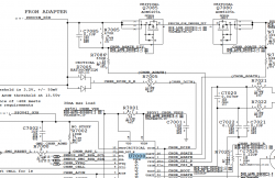
As can be traced in the attached picture, if you see 16.6v on Q7085-1/2/3, you should also see ~16v on D7005-3, and both side of R7005, and finally into U7000-2. Inside that chip, the 16v is converted into 5.1v that is called PP5V1_CHGR_VDD. This 5.1v is the internal power supply for the circuitry inside U7000 when DCIN magsafe is connected.
Q7085 is turned on when U7000 sensed that DCIN/ACOK signal is correct by bringing pin 1 to GND, thus enabling resistor divider R7085/R7086 to generate around 6-7v at the gate. It doesn't mean that the system will turn on if there are other problems. If Q7085 is turned on, Q7080 muust also turn on to allow magsafe power to be converted to 12v to reach the fuse by the battery connector.
 

Attachments

  • Screen Shot 2013-05-04 at 7.52.30 PM.png
    Screen Shot 2013-05-04 at 7.52.30 PM.png
    163.7 KB · Views: 847
Here's an idea: the left and right fan control for MBP comes from the SMC, however, these signals are gated by MOSFETs (Q5660 and Q5661, P/N 2N7002. AFAIK, A1278 only has ONE fan, so my schematic may not be exactly right, but good enough for discussion purposes. The fan is powered by 5v with these connector pinout:
1 - 5v input
2 - Tach output (fan speed to SMC)
3 - Fan speed control
4 - Ground

Since you are getting full fan speed, check pin 3 and see what voltage you see there. Normally this should be an "average" DC output of what the SMC think it should be as the SMC signal is pulse width modulated (PWM). In your case, it could be a steady logic signal. A scope (or logic probe) would have been very useful here. Backtracking, the SMC signal (FAN_CTL_0 or 1) is pulled up to 3.3v before wired to the SOURCE pin of the MOSFET and the GATE is always enabled by virtue of direct connection to 3.3v.

Thus using the "bypass" method indicated in the first message of this forum, SMC is probably not sending the FAN_CTL signal. Your no-boot state indicate a problem elsewhere. There is a logic gate that tell the system that "all" voltages are ok. I'd check that too.

cmdrdata - can you tell me where is that logic gate that tells all voltages are ok? Please look to my previous post #1526, I have a no-boot state issue as well. Like you said I would like to backtrack it only if I know the best point to start.

""Your no-boot state indicate a problem elsewhere. There is a logic gate that tell the system that "all" voltages are ok. I'd check that too.""
 
As can be traced in the attached picture, if you see 16.6v on Q7085-1/2/3, you should also see ~16v on D7005-3, and both side of R7005, and finally into U7000-2. Inside that chip, the 16v is converted into 5.1v that is called PP5V1_CHGR_VDD. This 5.1v is the internal power supply for the circuitry inside U7000 when DCIN magsafe is connected.
Q7085 is turned on when U7000 sensed that DCIN/ACOK signal is correct by bringing pin 1 to GND, thus enabling resistor divider R7085/R7086 to generate around 6-7v at the gate. It doesn't mean that the system will turn on if there are other problems. If Q7085 is turned on, Q7080 muust also turn on to allow magsafe power to be converted to 12v to reach the fuse by the battery connector.

I understood.
For a correct measurement I will install the board into the case again. Then I'll check the measured values ​​of the voltage divider.

Can a different port of the U7000 additionally prevent the function of the transistors?

I think that it could be possible, that there exists another fault.

Sincerely
dieett
 
cmdrdata - can you tell me where is that logic gate that tells all voltages are ok? Please look to my previous post #1526, I have a no-boot state issue as well. Like you said I would like to backtrack it only if I know the best point to start.

""Your no-boot state indicate a problem elsewhere. There is a logic gate that tell the system that "all" voltages are ok. I'd check that too.""

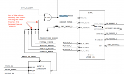
See the attached diagram (it isa for K90i but similar for other MBPs. Wired-OR means that these signals are usually floating to logic "1", probably around 3v, but even if only one of them returns a bad status, it will drag everyone down to logic zero, thus the system will fail to get an ALL_SYS_PWR_GOOD and thus will not allow the system to start-up.
 

Attachments

  • all-sys-pwr-good.png
    all-sys-pwr-good.png
    81.1 KB · Views: 1,972
I understood.
For a correct measurement I will install the board into the case again. Then I'll check the measured values ​​of the voltage divider.

Can a different port of the U7000 additionally prevent the function of the transistors?

I think that it could be possible, that there exists another fault.

Sincerely
dieett


The current measurement results:
- U7000 pin 1 to Zero - Q7085-5 = 16V;
- Voltage divider R7085/7086 = 6.4 V;
- However U7000-19/20 = 0V.

I now have to assume that U7000 is defective?
 
The current measurement results:
- U7000 pin 1 to Zero - Q7085-5 = 16V;
- Voltage divider R7085/7086 = 6.4 V;
- However U7000-19/20 = 0V.

I now have to assume that U7000 is defective?

If pin2 has ~16v and pin19 has 0v, then yes, I'd think that internal voltage regulator of U7000 that generate 5.1v is damaged/bad. Pin 20 is the same as pin19 except it passes thru a Zener diode, internally.
 
If pin2 has ~16v and pin19 has 0v, then yes, I'd think that internal voltage regulator of U7000 that generate 5.1v is damaged/bad. Pin 20 is the same as pin19 except it passes thru a Zener diode, internally.

Well then ...
Next, I found that U7200-13 = 0V. 5.33 V should be present here.
The control for U7941-3 0V [P5V3V3_REG_EN]. PP3V42_G3H is available.
Can I also come from a defective component here?
 
I’ve got a 2006 MacBook 1,1 A1181 with the dreaded Random Shutdown Problem.

Don’t know the history of the machine but it looks like it was never taken back to Apple for repair and has been mothballed for a very long time. Looks almost new and the battery is reporting 170 cycles, although it is dead and unusable.

Powered by the magsafe lead it will boot and run normally for about 15 minutes and then shutdown with an audible click.

It will only re-boot if the magsafe is disconnected for a few seconds and then replaced. Typically it will then run for about 5 minutes.

Subsequent re-starts shutdown earlier and earlier, until eventually it only gets halfway through the chimes!


Thinking at first it was a temperature issue, I have done the following:-

complete strip down and cleanup;
new thermal paste;
replaced heatsink (old one had cracked board at the sensors);
renewed and re-routed the heat sink temp sensor leads;
PRAM reset;
SMC check;
HD check and repair permissions;
RAM reseat.

The temps reported to iStat are all low/normal. CPU has never reported above 80°C. Occasionally heat sink 2 reports 126°C briefly before stepping down to around 40.

Starting up with the ‘temporary bypass’ from Dadioh’s original post makes no difference, except that the fan continues at high speed after shutdown until power is removed.

Console logs don’t seem to show anything unusual, at least nothing common to each shutdown.


I know this is MacBook ancient history and that Apple replaced/repaired back in the day. Does anyone have any ideas about the cause, or about what I try next?

All contributions gratefully received…thanks

I've got some more information about this problem, following my first post.

I've discovered that the machine boots and runs perfectly on a charged battery, continuing happily until the battery is discharged. In this case the magsafe plug has no led and does not charge the battery.

Removing the battery, magsafe lights green and machine boots and runs from 'cold' for about 15 minutes, then cuts out. Restarting after cut-out gets as far as the chimes and then cuts out, unless the magsafe is first disconnected for a few seconds, then the machine runs for about 2 minutes. It seems that disconnecting the magsafe for longer and longer periods gives more and more run time until we get back to the maximum of 15 mins

Can anyone point me in the right direction to start investigating this? I have schematic and some SMD experience but don't know enough about macs to diagnose.
 
See the attached diagram (it isa for K90i but similar for other MBPs. Wired-OR means that these signals are usually floating to logic "1", probably around 3v, but even if only one of them returns a bad status, it will drag everyone down to logic zero, thus the system will fail to get an ALL_SYS_PWR_GOOD and thus will not allow the system to start-up.

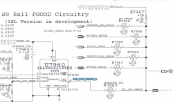
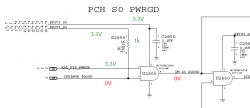
I verified these signals on my schematic (attached) and they are show 3.3V which I assume is the correct value when comparing to my other working LB.

CPUIMVP_AXG_PGOOD
P1V8S0_PGOOD
P5V3V3_PGOOD
CPUVCCIOS0_PGOOD
PVCCSA_PGOOD

R7962 feeds into our SMC with ALL_SYS_PWRGD which also has 3.3V

So is it safe to say the PWRGD has the correct values and I have to look somewhere else? If you agree, where can I trace the PWRGD for the GPU chip/video. Because I got the feeling it might be the video issue that is stopping the system from start-up.

Note: I also checked all SMBus connections including all the pullup resistors which all had proper values. So what should I check next?
 

Attachments

  • Capture1.PNG
    Capture1.PNG
    22 KB · Views: 405
  • Capture.PNG
    Capture.PNG
    105.8 KB · Views: 413
I verified these signals on my schematic (attached) and they are show 3.3V which I assume is the correct value when comparing to my other working LB.

CPUIMVP_AXG_PGOOD
P1V8S0_PGOOD
P5V3V3_PGOOD
CPUVCCIOS0_PGOOD
PVCCSA_PGOOD

R7962 feeds into our SMC with ALL_SYS_PWRGD which also has 3.3V

So is it safe to say the PWRGD has the correct values and I have to look somewhere else? If you agree, where can I trace the PWRGD for the GPU chip/video. Because I got the feeling it might be the video issue that is stopping the system from start-up.

Note: I also checked all SMBus connections including all the pullup resistors which all had proper values. So what should I check next?

I've not dealt too much into the rest of the startup, but if you noticed, since you got ALL_SYS_PWRGD at the correct state, your "State 0" is all OK, next you should be looking at S1 (State 1) and after that S2, S3,etc. These are the power sequencing states that the MBP goes thru to ensure that all devices comes up at the correct time. For example, it does you no good to look for S3 voltages/status if S1 or S2 were not successful.
 
I've not dealt too much into the rest of the startup, but if you noticed, since you got ALL_SYS_PWRGD at the correct state, your "State 0" is all OK, next you should be looking at S1 (State 1) and after that S2, S3,etc. These are the power sequencing states that the MBP goes thru to ensure that all devices comes up at the correct time. For example, it does you no good to look for S3 voltages/status if S1 or S2 were not successful.

This is new territory to me as well when it comes to startup states. Said that I'm having problems locating these (S1, S2, S3) on the schematic. Once I locate it I should be able to trace it and measure proper voltages.

There only thing that I found is the attached table with different states (S0, S3, S4, S5, G3Hot) see attached PDF. Again, not sure if this is it. :confused:
 

Attachments

  • state.PNG
    state.PNG
    6.2 KB · Views: 296
  • PowerControl.pdf
    43.8 KB · Views: 890
Backlit Keyboard connector repalcement

Does anyone know where I can get one of these or perhaps somebody is willing to send me one off a dead board. Thanks!!!
 
I've not dealt too much into the rest of the startup, but if you noticed, since you got ALL_SYS_PWRGD at the correct state, your "State 0" is all OK, next you should be looking at S1 (State 1) and after that S2, S3,etc. These are the power sequencing states that the MBP goes thru to ensure that all devices comes up at the correct time. For example, it does you no good to look for S3 voltages/status if S1 or S2 were not successful.

Well after some more tracing I discovered that I'm getting 0V instead of 3.3V on the Chipset Support circuit. The signal is CPUIMVP_PGOOD and if you look at my second screenshot it comes from U7400 and connects directly to U2850. Now, the challenge would be to discover what is causing my 0V. Would that be U7400 (which is pretty big IC) or the smaller U2850? Or maybe even something else. I'm just assuming this is the CPU signal for power good? So having 0V instead of 3.3V would explain my start-up issue?
 

Attachments

  • Capture4.PNG
    Capture4.PNG
    39.2 KB · Views: 423
  • Capture3.PNG
    Capture3.PNG
    19.9 KB · Views: 376
Last edited:
Well after some more tracing I discovered that I'm getting 0V instead of 3.3V on the Chipset Support circuit. The signal is CPUIMVP_PGOOD and if you look at my second screenshot it comes from U7400 and connects directly to U2850. Now, the challenge would be to discover what is causing my 0V. Would that be U7400 (which is pretty big IC) or the smaller U2850? Or maybe even something else. I'm just assuming this is the CPU signal for power good? So having 0V instead of 3.3V would explain my start-up issue?

Is pin1 of R2850 3.3v? if not you have to back track why the 3.3v (PP3V3_S0 is not so. If it is 3.3v, then track back CPUIMVP_PGOOD to determine why it is logic 0.
EDIT: U2850 is doing what it is supposed to do, i.e., any logic zero on it's input causes logic zero output. Only if BOTH inputs are logic high will the output go high.
 
Last edited:
Is pin1 of R2850 3.3v? if not you have to back track why the 3.3v (PP3V3_S0 is not so. If it is 3.3v, then track back CPUIMVP_PGOOD to determine why it is logic 0.

Sorry my fault, I recorded it on the paper but never transferred on the PDF copy (just updated now). So yes, I do have 3.3V on the pin1 of R2850.

Knowing that you think it is U7400 or U2850 causing our 0V? Tracking backwards SPUIMVP_GOOD goes directly to the pin19 of (U7400, 40pin IC)

Tracking forward it connects to U2850 (5pin) which is 'CMOS Single 2-Input AND Gate'
 
macbook pro mid 2009 who start's only "With temporrary by-pas"

i test the macbook pro with ASD 3S132, and its stop on:"Thermal Interface: TIM Test 75 percent GB" with error 39007. Any idea?
 

Attachments

  • Picture 1.png
    Picture 1.png
    604 KB · Views: 537
Is pin1 of R2850 3.3v? if not you have to back track why the 3.3v (PP3V3_S0 is not so. If it is 3.3v, then track back CPUIMVP_PGOOD to determine why it is logic 0.
EDIT: U2850 is doing what it is supposed to do, i.e., any logic zero on it's input causes logic zero output. Only if BOTH inputs are logic high will the output go high.

Hemh, U7400 has a few inputs and a couple of them are thermal sensors (inputs are identified with the word "IN" inside boxes with one end pointing toward the chip), so you need to know which one is in the wrong state. Signal with _L or connect to U7400 with a bubble/circle means that it should be logic 0 or ~0v, to be correct. All the others should be logic 1 or ~3v to be correct. Any of these input will cause CPUIMVP7 signal for U2850 to go to logic 0.
 
Hemh, U7400 has a few inputs and a couple of them are thermal sensors (inputs are identified with the word "IN" inside boxes with one end pointing toward the chip), so you need to know which one is in the wrong state. Signal with _L or connect to U7400 with a bubble/circle means that it should be logic 0 or ~0v, to be correct. All the others should be logic 1 or ~3v to be correct. Any of these input will cause CPUIMVP7 signal for U2850 to go to logic 0.

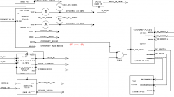
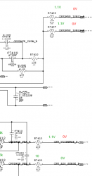
Ok...more tracing...I was studying more the CPU and AXG VCore Regulator circuit which consist our main IC U7400. So what I found out was that the whole circuit is fine (voltages and resistance) except:

CPUIMVP_PGOOD --this should be 3.3V instead of 0V
CPUIMVP_AXG_PGOOD --this should be 1.1V instead of 0V

So until I will have proper voltages on these two lines my board won't POST.

Now, since I got nominal VCC 5V to the U7400 IC and other voltages are fine I have a reason to believe this chip is fine. And the reason why is because the 4 INs
that should carry 1.1V instead have 0V thus the U7400 is outputting 0V and saying CPU power is no good.

Please look at my screenshot and these four signals the bottom two are coming from CPU Power circuit if I want to trace it back.

The top two are coming from the CPU Voltage and Current Sensing.
 

Attachments

  • Capture5.PNG
    Capture5.PNG
    20 KB · Views: 331
Register on MacRumors! This sidebar will go away, and you'll see fewer ads.