Become a MacRumors Supporter for $50/year with no ads, ability to filter front page stories, and private forums.
MBP 13 Not Charging

It works great on battery power. Trouble is I can only charge the battery by connecting it to a different logic board.
Here's what I have observed.
No lights on magsafe plug - magsafe works fine on other machines.
If I unplug the battery from the board, the magsafe lights up bright green but flashes off - very briefly - about every second. Pulsing off?
As soon as I reconnect the battery, the light goes out.
No A/C power in system profiler - battery is good.
SMC reset - no change.
Board is very clean - no sign of any liquid or other damage/corrosion.
Check fuses, resistors and voltages referenced in this thread - all normal as far as I can see.
Just wondering if anyone recognizes the "pulsing off" green light as a symptom?
Any and all suggestions greatly appreciated!
 
Pp3v3_s0_lcd_f

Hi everyone!

Props to Dadioh for starting this thread, and to all of you who contribute. This is a great resource and I will try to help as much as I can in the future.


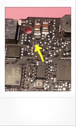
But for now I have a problem of my own. My 2010 MBP13 (820-2879-B board) had a burned inductor at the beginning of the signal PP3V3_S0_LCD_F (page 67 in schematics). I have replaced the inductor but the resistance between signal and ground seems too low.
It reads 3.5kohm without the LVDS cable connected and I believe it should be about 40kohm.

I am wondering if anyone here could measure the correct resistance for me from a working board?

Position is L9008 and it is located just to the right of magsafe connector (see attached picture).

Any help would be greatly appreciated!

Best wishes - Andreas
 

Attachments

  • image_01.png
    image_01.png
    545.3 KB · Views: 1,464
Hi everyone!

Props to Dadioh for starting this thread, and to all of you who contribute. This is a great resource and I will try to help as much as I can in the future.


But for now I have a problem of my own. My 2010 MBP13 (820-2879-B board) had a burned inductor at the beginning of the signal PP3V3_S0_LCD_F (page 67 in schematics). I have replaced the inductor but the resistance between signal and ground seems too low.
It reads 3.5kohm without the LVDS cable connected and I believe it should be about 40kohm.

I am wondering if anyone here could measure the correct resistance for me from a working board?

Position is L9008 and it is located just to the right of magsafe connector (see attached picture).

Any help would be greatly appreciated!

Best wishes - Andreas

6,7k Ohm
 
Hi everyone!

Props to Dadioh for starting this thread, and to all of you who contribute. This is a great resource and I will try to help as much as I can in the future.


But for now I have a problem of my own. My 2010 MBP13 (820-2879-B board) had a burned inductor at the beginning of the signal PP3V3_S0_LCD_F (page 67 in schematics). I have replaced the inductor but the resistance between signal and ground seems too low.
It reads 3.5kohm without the LVDS cable connected and I believe it should be about 40kohm.

I am wondering if anyone here could measure the correct resistance for me from a working board?

Position is L9008 and it is located just to the right of magsafe connector (see attached picture).

Any help would be greatly appreciated!

Best wishes - Andreas

Hi, i have a working board here and i've measured both sides of the inductor to ground and i get a reading of 4.8M ohm. This measurement was taken with the LVDS cable disconnected from the board and the board was powered off.

regards Rog
 
Hi all,

The quest continues: adding the missing Schottky diode (see post 1471) has not fixed my problem :eek:, but there's power on pin 2 of the charger IC (U7000), unlike before.

The situation:
  • G3HOT is ehm, HOT ;)
  • 16,5V present from charger
  • Voltages on charger chip as indicated in image (no value mean 0V (IC only))
  • Q7000 drain = 0V
  • Drumroll......... NO CHARGING LIGHT, NO CHIME, NO SCREEN, NO NUTTIN'

Bit lost a the moment, so please help!


This bit leaves me with a few questions:

  1. Is the voltage after R5087 a reference voltage which is pulled down whenever it is 'thought' the charger is not present or faulty?
  2. Which IC pulls this signal down normally and when? Something to do with AMON right?
  3. Should the Q7000's drain be hot in the current situation or should the gate signal be low for this? (I always confuse my FETs ;), I think it's the latter)
  4. Shouldn't there be voltage on VDD and VDDP? If so, where to look?

Thanks guys, any help is appreciated for this mechanical engineer :D

Rick


PS Is there some kind of attempt on explaining ISL6258A somewhere, or even the total MBP power logic sequence?

Hi again, following on from my original post to you, I have now had the good fortune of fixing a board which had the nearly the exact same problems as yours, my G3HOT does not get Hot. With regards to 'no led' on the magsafe, i replaced the usual suspects U6915 and Q6910 and the led now works, the board detects the presence of DC voltage.

Next i tried to power on with only the battery conntected, nothing happened. So, removing the battery I plugged in the magsafe (green led on) and proceeded to take voltage measurements. Firstly I checked at fuse F7000 to make sure i had 12.5V, this supplies PPBUS_G3H. I got 12.5v so I moved onto next area, making sure I had 3.3v at L7220, this supplies PP3V3_S5_REG. I didnt get 3.3v at L7220 so i presumed the IC U7200 (TPS51125) had gone faulty. Further visual inspection around U7200 i noticed a pcb track from pin #16 had been eaten away by liquid. The IC looked in bad state too. I replaced U7200 because in my experience when a pcb track has been damaged by liquid, it tends to take out the IC as well. Having replaced U7200 and repaired pcb track to pin #16, I checked back at L7220 and found I now have 3.3v. I therefore added RAM to the memory slot, connected just the fan and speakers, connected keyoard, pressed the power button and guess what, it work, fan started to spin and I heard the chimes. I powered down, plugged in the LCD screen, powered back on again and it displayed with the flashing folder icon..success :)

I have other M97's to repair and if they are any different in repair method, i will let you know.

regards Rog
 
MBP 13" without Display output

A good day to the community.
I read with interest the insightful contributions to fault finding.

I can find help here!
I have a 820-2879-B and 820-2936-B to repair. both with water damage.
First, Please
where do I get the board view of both LB? The questions for disposal in post # 1429 are not readable.
 
MBP13 2010 Slow on Battery - VPOR Sensor error

I have seen it mentioned a few times that people have had issues with their Macbook Pro running slow on battery power but working on charger just fine. I finally came across a logic board that was doing just this. The symptoms were:

1) Runs fine on charger. No slow down or lag.
2) Unplug the charger and everything slows to a crawl. Kernel Task is using up full CPU bandwidth.
3) AHT reports a sensor error 4SNS/1/40000001:VPOR

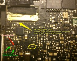
I started looking around on the logic board to see what I could find out. I came across a liquid damaged portion of the board that did not look great. As I was measuring resistance across one resistor it moved... not good. I desoldered it and repaired the landing pad and replaced the resistor with a new one from a spare board. I then noticed a test point that looked rather corroded and indeed the entire copper dot had rotted out and opened up the trace between two capacitors. I repaired the trace with a small mod wire and...

Problem resolved. Just thought I would report this in case anyone had run into this. It may be a good idea to have a look at these particular circuits on your logic board.

The model is a Macbook Pro 13" mid-2010 model. The photo is one I dug out of my files so ignore the notes concerning backlight voltage. However, see the red and green notes concerning the bad traces I discovered.

Hope this helps someone rescue a Macbook. :)
 

Attachments

  • VPOR Error Slow on battery fix.jpeg
    VPOR Error Slow on battery fix.jpeg
    349.6 KB · Views: 4,190
2008 macbook pro 15" doesn't boot

Hi Everybody,

I've a macbook pro 15" (part number of the logic board: 820-2532-a).
It turns on, but I doesn't hear the apple chime, the screen displays nothing and the sleep led is lighting continously. (First I tried the SMC, PRAM reset..)
Then I thought that it was a problem of the GPU or memory of the GPU. I heated these, but it wasn't fixed. Next I flashed the SPI flash to a new bios dump, but the logic board didn't boot. I tried to change the SMC, but it wasn't booting. Has Everybody any idea?

Thank you!

Did you try the SMC bypass method in the first post?

There are gazillions of things that can be wrong with the logic board that can prevent a Macbook from chiming. Hard to give any one magic answer. If the SMC bypass method works however, you can get further clues from the sensors once it boots into OS X.

Hello Dadioh,

Thanks your answare.
Yes, I tried it. The logic board turns on without smc - with smc bypass, but it isn't still booting. :(
In this case the sleep led isn't lightning continously, but it is understandable, because the smc doesn't drive the sleep led... But it isn't booting, and the screen is "dark".

Do you have a way of outputing the display to an external monitor?. Reason i ask is because i have been caught out a couple of times of thinking a logic board is not powering based on the boot chimes and lcd display. A collegue of mine who tests the boards i repair mentioned that in some cases, the volume level drop to zero if a logic board crashes in the process of doing something, so when you take out the board to investigate the problem, you dont hear the boot chimes and therefore think the board is not posting. The only way to correct this problem is too boot into the OS and increase the level on the voliume bar. The 'dark' screen could be the backlight gone faulty so it is therefore possible that your board could be booting using the SMC bypass, it is just that the 'dark' lcd and no boot chimes is making you think it is not booting at all. Hence the question about the external display. Have the harddisk connected with an external display, carry out the SMC bypass method and see if it displays on the external screen, if it does then we know the 'dark' lcd is a backlight issue.

If the board powers (fan spins) but you dont see anything on the external monitor then it will be a boot issue which needs to be investigated.
 
Hi, i have a working board here and i've measured both sides of the inductor to ground and i get a reading of 4.8M ohm. This measurement was taken with the LVDS cable disconnected from the board and the board was powered off.

regards Rog


Thanks laptech and mousepad. Two very different readings there, but they both are different from mine and that helps alot.

I'll try to lift a few caps and resistors and see if that changes anything. I'll be back with more questions!

/ Andreas

----------

A good day to the community.
I read with interest the insightful contributions to fault finding.

I can find help here!
I have a 820-2879-B and 820-2936-B to repair. both with water damage.
First, Please
where do I get the board view of both LB? The questions for disposal in post # 1429 are not readable.

I can get the file for 2879 board. PM me if you still need it!


/ Andreas
 
Do you have a way of outputing the display to an external monitor?. Reason i ask is because i have been caught out a couple of times of thinking a logic board is not powering based on the boot chimes and lcd display. A collegue of mine who tests the boards i repair mentioned that in some cases, the volume level drop to zero if a logic board crashes in the process of doing something, so when you take out the board to investigate the problem, you dont hear the boot chimes and therefore think the board is not posting. The only way to correct this problem is too boot into the OS and increase the level on the voliume bar. The 'dark' screen could be the backlight gone faulty so it is therefore possible that your board could be booting using the SMC bypass, it is just that the 'dark' lcd and no boot chimes is making you think it is not booting at all. Hence the question about the external display. Have the harddisk connected with an external display, carry out the SMC bypass method and see if it displays on the external screen, if it does then we know the 'dark' lcd is a backlight issue.

If the board powers (fan spins) but you dont see anything on the external monitor then it will be a boot issue which needs to be investigated.

Thanks your answer.
This is not a backlight problem, because I illuminated the display from outside, across the apple sign, but nothing is showed on the display. Next I tried with the external monitor, because I taught that the lcd was wrong, but it wasn't work with that too. I think that is the sleep led is lighting continously that means that the boot process is stopped by something. But I don't have any idea what the cause of this is?!?
 
820-2679.brd File

Thanks laptech and mousepad. Two very different readings there, but they both are different from mine and that helps alot.

I'll try to lift a few caps and resistors and see if that changes anything. I'll be back with more questions!

/ Andreas

----------


I can get the file for 2879 board. PM me if you still need it!


/ Andreas

Thank you.
The file that I had has destroyed itself. They had in use. The next day she was not there, strange.
Is there a specific reference source for board-view.brd files?


bga-rework.ettelt@online.de

Beste Grüsse aus Deutschland: Apfel:
 
Thank you.
The file that I had has destroyed itself. They had in use. The next day she was not there, strange.
Is there a specific reference source for board-view.brd files?


bga-rework.ettelt@online.de

Beste Grüsse aus Deutschland: Apfel:


There are a number of sources that sell schematics and board layout files, and there are also alot of places where you can find them for free. Try searching the net and I'm sure you will find the layout for the other board.
 
820-2327-A SMC not functioning

Hi, i hope this is ok to put this here.

I have repaired two 820-2327-A boards now that have failed to post either with battery or magsafe connected. When pressing the power button i get no function whatsoever. The magsafe LED is OFF, there is no 3.2v (SYS_ONEWIRE) @ pin#6 Q6920. Both logic boards were liquid damaged which was cleaned. Taking mesaurements, I got all the main voltages that I am supposed to get so I knew it had something to do with the SMC because that is what controls the power on function to the board. Upon closer inspection of the SMC and surrounding components I noticed that many of the resistors had become corroded and when I took them off I could see that some of the liquid had eaten away at the solder and therefore one side of the resistors was not making contact to it's solder pad. I've included a picture of the parts that i took off and replaced (marked in yellow). The parts came from a scrapped logic board i had. Once replaced, I connected magsafe and got the green led on, plugged in the RAM, speaker,fan and keyboard, pressed the power button and hey presto, it worked, on both boards.


attachment.php
 

Attachments

  • SMC_parts.bmp
    900.1 KB · Views: 7,060
Last edited:
Hi, i hope this is ok to put this here.

I have repaired two 820-2327-A boards now that have failed to post either with battery or magsafe connected. When pressing the power button i get no function whatsoever. The magsafe LED is green therefore part of the SMC and DC detection circuit is working. Both logic boards were liquid damaged which was cleaned. Taking mesaurements, I got all the main voltages that I am supposed to get so I knew it had something to do with the SMC because that is what controls the power on function to the board. Upon closer inspection of the SMC and surrounding components I noticed that many of the resistors had become corroded and when I took them off I could see that some of the liquid had eaten away at the solder and therefore one side of the resistors was not making contact to it's solder pad. I've included a picture of the parts that i took off and replaced (marked in yellow). The parts came from a scrapped logic board i had. Once replaced, I connected the RAM, speaker,fan and keyboard, pressed the power button and hey presto, it worked, on both boards.


Image

Good work laptech, and thanks for sharing. If everyone that has been successful in restoring their systems and detailed what they did to get there, then Dadioh's goal of creating this specific forum will help everyone immensely. I've not been posting due to health issues, but do read this forum regularly whenever I can. I have two 11" MBAs (A1370s) waiting to be fixed (both has liquid damage), but just don't have the energy or time or workspace to work on them.

PS: Your fixes as shown here is a clue to others with issues. It seemed to me that modern logic boards are very sensitive to corrosion due to any liquid and thus caused component detachment and solder breaks. Perhaps the solder connectivity of SMD components when they are first manufactured (via flow/reflow soldering) are very minimal and thin thus resistors/caps/and ICs that are just barely connected.
 
Last edited:
Good work laptech, and thanks for sharing. If everyone that has been successful in restoring their systems and detailed what they did to get there, then Dadioh's goal of creating this specific forum will help everyone immensely. I've not been posting due to health issues, but do read this forum regularly whenever I can. I have two 11" MBAs (A1370s) waiting to be fixed (both has liquid damage), but just don't have the energy or time or workspace to work on them.

PS: Your fixes as shown here is a clue to others with issues. It seemed to me that modern logic boards are very sensitive to corrosion due to any liquid and thus caused component detachment and solder breaks. Perhaps the solder connectivity of SMD components when they are first manufactured (via flow/reflow soldering) are very minimal and thin thus resistors/caps/and ICs that are just barely connected.

cmdrdata, you are exactly correct. Due to the changes in law regarding the checmical makeup of solder and fluxes, modern day electronics cannot standup to liquid corrosion like there counterparts could many years before them. I've been involved in SMD repair/rework from the late 80's when I used to work for NEC mobile phone division. Lead is a good resistor of water, hence why it is used alot on buildings still today and as we know, solder is made up of a combination of lead and tin. Electronics using solder before the late 90's could stand upto alot of liquid spills but due to new laws requiring the reduction of lead in solder, it means todays solder can not stand upto todays liquid spills and as such you get 'solder corrosion'. This is where the liquid gently eats away at the tin part in the solder and you eventually get whats called a 'cold solder' joint. This is where the solder is not making 100% contact with the solder pad thus creating a 'dry joint'.

All the parts i changed had this 'solder corrosion'. Usually you can tell by doing a continuity test with a multimeter between the two connecting components but in the case of the SMC which is a BGA chip, you cannot carry out this task, so looking through a good microscope is your only option. On logic boards with a liquid spill, you will see many types of corrosion on the board but it is one in particular that you are looking for. It is very diffcult to describe it in words so when my usb microscope arrives, i hope it will give me good enough definition so i can show what others need to be looking for.

regards Rog

I should like to thank at this point for the helpful tips and very important background information.

With two boards water damage: A1278 (820-2879) and (820-2936 B) I have to fight.
An important reason for me to purchase a stereo Microscope.

Need help for the 820-2936-B:
The board starts briefly and goes out again. This is repeated at intervals of 5 seconds.
Where should I start looking?

Friendly greetings
dieett

First, you need to eliminate if anything connected to the logic board is causing the problem. The best way to achieve this is to only have the MAGESAFE (make sure green led is on), FAN & SPEAKERS connected. You do not need the keyboard connected because I have supplied a picture on what pin on the keyboard connector you need to short to ground. I find it best to use a fine tip pair of tweezers, one end touching pin#5 of the keyboard connector and the other end a suitable ground point. This acts in the same way as pressing the power button on the keyboard. Touch pin#5 on the KBC (keyboard connector) and you should see the fan spin and hear the memory error audio tone.

Listening for the memory error audio tone is the first check because this will tell you if the Northbridge (NB) is initially functioning because for the NB to determine if there is no memory present, all the initial main voltage and data signals have to be present. If you hear the memory error audio tone, you then need to procceed onto the next step which is to determine if the error is being caused by something during the POST procedure but if you do not hear the memory error audio tone then this indicates that the NB is not functioning and therefore you have a either have a faulty NB because it is shorting out when voltage gets to is or a data line is mis-reporting hence the 5 sec interval restarts or you have a voltage issue that when voltage passes through one of the components, the shorts causes the component to act in an unsual manner.

This part is only required if you hear the memory error audio tone and the original error has not occured.

You have now determined that the original fault does not occur when there is no RAM present because the logic board stays powered on and you hear the constant memory error audio tone.

Plug in the RAM and make sure the CPU heatsink is attached. Now repeat the power on method as described above. This time due to the RAM being fitted, the board should try and post. The 5 sec interval error may appear at this stage.

The whole point of doing this test procedure with the RAM removed and then the RAM fitted is we need to determine if the 5 sec interval fault is being caused by a power issue or if the fault is being caused when the logic board tries to got through it's power and post procedure.

Wait and see what happens now when the board is powered on with the RAM present. Does the original 5 sec interval fault occur or do you hear the post chime and notice the fan just happily doing it's job of keeping the board cool? If at this point the original fault does not occur, then this indicates that something connected to the logic board is causing the problem.

At this point you would then start connecting things back together to see if the original fault occurs. So, connect the LCD first, then repeat the power on test and wait to see if the fault occurs. You keep adding parts to the logic board one by one until you see with item is producing the fault you've described.

regards Rog

attachment.php
 

Attachments

  • KBD_ONOFF_PIN.bmp
    900.1 KB · Views: 3,642
First, you need to eliminate if anything connected to the logic board is causing the problem. The best way to achieve this is to only have the MAGESAFE (make sure green led is on), FAN & SPEAKERS connected. You do not need the keyboard connected because I have supplied a picture on what pin on the keyboard connector you need to short to ground. I find it best to use a fine tip pair of tweezers, one end touching pin#5 of the keyboard connector and the other end a suitable ground point. This acts in the same way as pressing the power button on the keyboard. Touch pin#5 on the KBC (keyboard connector) and you should see the fan spin and hear the memory error audio tone.

Listening for the memory error audio tone is the first check because this will tell you if the Northbridge (NB) is initially functioning because for the NB to determine if there is no memory present, all the initial main voltage and data signals have to be present. If you hear the memory error audio tone, you then need to procceed onto the next step which is to determine if the error is being caused by something during the POST procedure but if you do not hear the memory error audio tone then this indicates that the NB is not functioning and therefore you have a either have a faulty NB because it is shorting out when voltage gets to is or a data line is mis-reporting hence the 5 sec interval restarts or you have a voltage issue that when voltage passes through one of the components, the shorts causes the component to act in an unsual manner.

This part is only required if you hear the memory error audio tone and the original error has not occured.

You have now determined that the original fault does not occur when there is no RAM present because the logic board stays powered on and you hear the constant memory error audio tone.

Plug in the RAM and make sure the CPU heatsink is attached. Now repeat the power on method as described above. This time due to the RAM being fitted, the board should try and post. The 5 sec interval error may appear at this stage.

The whole point of doing this test procedure with the RAM removed and then the RAM fitted is we need to determine if the 5 sec interval fault is being caused by a power issue or if the fault is being caused when the logic board tries to got through it's power and post procedure.

Wait and see what happens now when the board is powered on with the RAM present. Does the original 5 sec interval fault occur or do you hear the post chime and notice the fan just happily doing it's job of keeping the board cool? If at this point the original fault does not occur, then this indicates that something connected to the logic board is causing the problem.

At this point you would then start connecting things back together to see if the original fault occurs. So, connect the LCD first, then repeat the power on test and wait to see if the fault occurs. You keep adding parts to the logic board one by one until you see with item is producing the fault you've described.

regards Rog

Image


Thanks for the detailed description.

First of all:
The Board has been removed and the RAM Components and the keyboard also.
A MAG-Save is connected. LED is not leichtet. As far as no other reaction.
Only when I use the battery, the fan starts without keyboard. For a moment. After 5 seconds it starts again.
The speaker is doing a fine crackling sound when it starts up again.
In this respect I think it is a defective board.

Probably there is a short circuit.
What I lack for signal tracking is the Board view file.

Which memory error audio tone can be expected?

greetings from germany
 
Last edited:
Thanks for the detailed description.

First of all:
The Board has been removed and the RAM Components and the keyboard also.
A MAG-Save is connected. LED is not leichtet. As far as no other reaction.
Only when I use the battery, the fan starts without keyboard. For a moment. After 5 seconds it starts again.
The speaker is doing a fine crackling sound when it starts up again.
In this respect I think it is a defective board.

Probably there is a short circuit.
What I lack for signal tracking is the Board view file.

Which memory error audio tone can be expected?

greetings from germany

OK, no green led on magsafe means you have a DC detection fault on the board. Using the battery be used. With RAM removed, if the NB is initial working you should hear a repeated beep tone. Usually when laptops have no memory they give out a special memory beep code indicating that the board has a memory issue. With the this logic board if the RAM is removed, the logic board should keep giving off an audiable beep and will keep doing so until you removed the power source. The crackling sound could be the memory error beep but it could be the audio section of the board is damaged by the liquid hence why the crackling instead of a clear BEEP sound. If you notice the fan spining then stop, then spin then stop, which mimics the 5 sec interval error you mentioned then it would appear you have a power supply issue somewhere on the board and when the voltage hits that faulty part, the board resets itself.

The board view and schematic for your logic board can be found in this thread. I found it while looking through the many pages.

regards Rog


Thank you for your information.
Next, I need to see that I get the board view. The schematic is available.

If you still could give a hint in which direction I have to look ... I have been more than two days on the internet looking after 820_2936-B (K90i).

greeting
dieett
 
LB#820-2936_MBP_13_A1278_k90i

Thank you for your information.
Next, I need to see that I get the board view. The schematic is available.

If you still could give a hint in which direction I have to look ... I have been more than two days on the internet looking after 820_2936-B (K90i).

greeting
dieett

Finally I found what I was looking for.
Here is the file of the Board view [820-2936]
 

Attachments

  • LB#820-2936 Macbook_13_A1278_K90i-brd.zip
    465.4 KB · Views: 690
Register on MacRumors! This sidebar will go away, and you'll see fewer ads.