Become a MacRumors Supporter for $50/year with no ads, ability to filter front page stories, and private forums.
I've read a lot in this thread and it gave me some hope to get my macbook 13" 2010 running again. A few weeks ago, the macbook suddenly powered off. Turning it on worked, but during reboot the macbook powered off again. Since then the charger only lights with a really dim green light (hardly to see in daylight) and never got on again. Pressing the battery button does also not show any result.

I tried the procedure from post 1 but unfortunately nothing happens.

The only thing I can remember I have done before, was cleaning the keyboard with a damp (not wet) microfiber cloth.

Any idea if this macbook is finally gone?
 
I would have thought so to but there must be some other resistors or something along that path.

Yes, I used the board view to locate the resistors by part number and both resistors measured 2.6 when measured end to end.

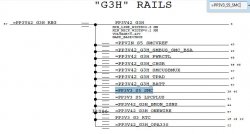
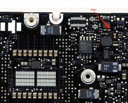
I am measuring G3hot from the bottom pad located in this picture ( this is not my board just using it as a reference)

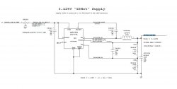
OK. That explains it. The pad that you are treating as G3Hot is not actually G3Hot. It is the Debug Power Button and if you follow it through the schematic you will see that is has a 10K pullup resistor to the actual G3Hot signal. So you are measuring the 2.6K + 10K (and possibly some other parallel paths).

This is all a moot point for your case since I think you have established that you do not have an issue with the pullups on the i2c bus. But possibly useful for others who assume that this pad is G3Hot. It is still useful to measure this pad when trying to determine if G3 Hot is present. Just don't use it if you are trying to diagnose something referenced to G3Hot.
 

Attachments

  • Debug_Power_Button.jpg
    Debug_Power_Button.jpg
    143.3 KB · Views: 429
  • PP3V3_S5_SMC.jpg
    PP3V3_S5_SMC.jpg
    59.3 KB · Views: 434
  • G3Hot.jpg
    G3Hot.jpg
    68.2 KB · Views: 583
OK. That explains it. The pad that you are treating as G3Hot is not actually G3Hot. .
Okay, I'm sorry about that. Every time I have seen someone reference G3Hot it was in regards to that pad. I should have asked.

In looking at the schematics you posted I 'm still not sure where exactly I should have been testing G3hot from and where it is located on the board. I'd like to know for future testing purposes.

Also, do you have any suggestions on what to test next?
 
bump

Hi all.

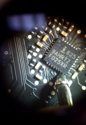
The U7000 (ISL6259AHRTZ) on my K90i is getting very hot in a short
time after plugging in the power connector. This started after having
accidentally shorted C7050.

The cap seems fine (desoldered, measured no short).
Is it possible that some other component is broken or do I have to
replace U7000?

I read somewhere in this thread that U7000 has its own power supply
depending on CHGR_DCIN (measured 16.5V) and the battery (didn't
measure that one). However, there's only 0.5V on R7001.
U7000 => broken?

Thanks

The ISL6259 generates its own 5V power and that is what you should see on R7001. If you have 0.5V then it sounds like the ISL6259 (U7000) has failed.

I have replaced lots of these 6258 and 6259's. I buy them 10 at a time :) They seem to be a common failure point.
 
Okay, I'm sorry about that. Every time I have seen someone reference G3Hot it was in regards to that pad. I should have asked.

In looking at the schematics you posted I 'm still not sure where exactly I should have been testing G3hot from and where it is located on the board. I'd like to know for future testing purposes.

Also, do you have any suggestions on what to test next?

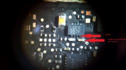
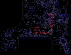
Pin 4 of the G3Hot power supply on the MBP13 2009 and 2010 models is at the top of the board. See attached. I put my probe on the cap since it is easier and safer than trying to get onto pin 4 of the supply.
 

Attachments

  • G3Hot_MBP13_2009.jpeg
    G3Hot_MBP13_2009.jpeg
    826 KB · Views: 782
Pin 4 of the G3Hot power supply on the MBP13 2009 and 2010 models is at the top of the board. See attached. I put my probe on the cap since it is easier and safer than trying to get onto pin 4 of the supply.

Thank you, my board is a little different but I believe I found it.

What components are next in the path of the battery communicating with the SMC? I have the schematics but I haven't quite figured out how to read them. Any tips on how to find this information by referencing the schematics would be greatly appreciated this way I can start doing my own testing.
 

Attachments

  • use when debugging - start of G3Hot_MBP13_2009.jpg
    use when debugging - start of G3Hot_MBP13_2009.jpg
    342.3 KB · Views: 468
Thank you, my board is a little different but I believe I found it.

What components are next in the path of the battery communicating with the SMC? I have the schematics but I haven't quite figured out how to read them. Any tips on how to find this information by referencing the schematics would be greatly appreciated this way I can start doing my own testing.

That is the right spot to measure G3Hot.

As far as reading schematics that is something you will need to practice. It is an essential skill if you are going to get into more advanced troubleshooting.

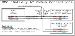
The starting point is the clip below. The underlined terms are the "net" names for the signals. When you see them connected together logically like this they are the same electrical connection with different names. Red underlined are the clocks. Blue is data. You copy the net name into the search function and find all instances in the schematic to determine the interconnections. Then you can use boardview to find the component locations. I much prefer using Adobe PDF Reader for this rather than Preview.

Most of the time when I am having trouble with I2C bus communications issues between the SMC, Battery, and Charger it turns out to be either bad pullup resistors or a bad ISL6258/9 or bad SMC. I suppose it could be a bad capacitor (shorted) on the lines but I have not seen this yet.

Good luck.
 

Attachments

  • Charger_i2c.jpeg
    Charger_i2c.jpeg
    329.4 KB · Views: 720
As far as reading schematics that is something you will need to practice. It is an essential skill if you are going to get into more advanced troubleshooting.

The starting point is the clip below. The underlined terms are the "net" names for the signals. When you see them connected together logically like this they are the same electrical connection with different names. Red underlined are the clocks. Blue is data. You copy the net name into the search function and find all instances in the schematic to determine the interconnections. Then you can use boardview to find the component locations. I much prefer using Adobe PDF Reader for this rather than Preview.


Good luck.

This is starting to make a little more sense. I was confused on how exactly you know which way the path is moving from component to component. I'm not sure if I have this right though, is clock path the one receiving the data and data path sending the data?

Most of the time when I am having trouble with I2C bus communications issues between the SMC, Battery, and Charger it turns out to be either bad pullup resistors or a bad ISL6258/9 or bad SMC. I suppose it could be a bad capacitor (shorted) on the lines but I have not seen this yet.

Good luck.

Is there a way of testing the ISL6258/9 and SMC individually or is it a matter of testing all of the fuses, caps, resistors etc before and after the component to verify that its functioning properly?
 
Last edited:
MacBooK Pro 13" 2010 No boot/Power

Dadioh, long time no talk. I have a 13" 2010 MBP no power, no charge, no G3HOT. No signs of liquid damage. I am stumped. Have 16.5 volts coming in to U6990, but nothing coming out when checking the capacitor by pin 4. What could be pulling this down?
 
Hi and greetings from Estonia.
As i'm not an expert on electronics yet, i thought you might point me in the right direction. Macbook Pro 13" 2011 model.
It powers on and charges the battery from magsafe, even works on battery. The only thing is, it doesn't start from battery.
What i've done so far is measuring G3Hot, which all seems present. Could it be some pullup resistors? If yes, how can i find them physically on board, to measure?
I really need to get this thing running, so i appreciated all the help i can have.:)
 
820-2914 schematic

Hi folks. Thought I'd share a schematic for 820-2914. 2011 Macbook Pro 17". I don't have the board view - anyone else got it?

I've got a pristine Macbook Pro with water damage that's been sitting here for months. Green Magsafe light but battery not charging and laptop dead. There's a bit of heat from the heatsinks when trying to charge - probably not a good sign.

Is there a way to charge the battery externally? I've seen it in this thread in the past but didn't quite understand it.

Here's the voltages at the battery connector. Any ideas? Difficult to find the charging resistors without the boardview...
 

Attachments

  • 820-2914.zip
    2.2 MB · Views: 1,591
  • voltages.jpg
    voltages.jpg
    64.4 KB · Views: 349
Last edited:
NEW MACBOOK DIFFERENT PROBLEM no G3HOT

Ok, so I put down the MacBook we have been troubleshooting to give my brain a rest. The new MacBook is the same exact model but this one has no G3HOT at all.

I started at the adapter and worked my way through testing everything up to U7000 and noticed I had 16.85v going through R7005 into U7000 but nothing coming out of U7000 on pin 14 I'm assuming this means U7000 needs to be replaced on this one?
 

Attachments

  • BAD U7000.jpg
    BAD U7000.jpg
    302.7 KB · Views: 698
Ok, so I put down the MacBook we have been troubleshooting to give my brain a rest. The new MacBook is the same exact model but this one has no G3HOT at all.

I started at the adapter and worked my way through testing everything up to U7000 and noticed I had 16.85v going through R7005 into U7000 but nothing coming out of U7000 on pin 14 I'm assuming this means U7000 needs to be replaced on this one?

How are you testing that pin 14? What do you use to get in there? Mine has the same problem. fuses are all good, i get power to the U6990 but nothing out
 
Last edited:
How are you testing that pin 14? What do you use to get in there? Mine has the same problem. fuses are all good, i get power to the U6990 but nothing out

Hi mac-n-sauce, I am touching the probe directly to pin 14.
 

Attachments

  • 2013-07-02_16-09-30_906.jpg
    2013-07-02_16-09-30_906.jpg
    314 KB · Views: 621
Dadioh, long time no talk. I have a 13" 2010 MBP no power, no charge, no G3HOT. No signs of liquid damage. I am stumped. Have 16.5 volts coming in to U6990, but nothing coming out when checking the capacitor by pin 4. What could be pulling this down?

With power removed check the resistance between pin 4 and ground. I seem to recall it should be up in the 10's of kohm (going from memory). If you are seeing something in the single digit kohm or less then you may have a problem. Maybe check a known good board for a reference of what it should be.

Now if it does turn out to be low then you have a fun job. G3Hot feeds so many circuits and finding the one that is dragging it low will take a lot of component lifting and measurements. From past experience check the ISL6259 charger device. They are a common failure point particularly for liquid damaged units.

----------

Hi and greetings from Estonia.
As i'm not an expert on electronics yet, i thought you might point me in the right direction. Macbook Pro 13" 2011 model.
It powers on and charges the battery from magsafe, even works on battery. The only thing is, it doesn't start from battery.
What i've done so far is measuring G3Hot, which all seems present. Could it be some pullup resistors? If yes, how can i find them physically on board, to measure?
I really need to get this thing running, so i appreciated all the help i can have.:)

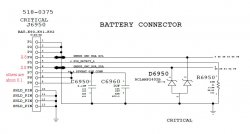
Check pins 4 and 6 on the battery connector. Those are the i2c communications from the battery to the charger and SMC. With system running they should be 3.4V. If not then you have a problem on that bus and SMC will not recognize battery -> will not start from battery.
 
With power removed check the resistance between pin 4 and ground. I seem to recall it should be up in the 10's of kohm (going from memory). If you are seeing something in the single digit kohm or less then you may have a problem. Maybe check a known good board for a reference of what it should be.

Now if it does turn out to be low then you have a fun job. G3Hot feeds so many circuits and finding the one that is dragging it low will take a lot of component lifting and measurements. From past experience check the ISL6259 charger device. They are a common failure point particularly for liquid damaged units.

I get a measurement of 2.
How do I verify that the ISL6259 is bad. Pin 14 is basically 0v I do get 16.75v coming in through the resistor R7010
 
Ok, so I put down the MacBook we have been troubleshooting to give my brain a rest. The new MacBook is the same exact model but this one has no G3HOT at all.

I started at the adapter and worked my way through testing everything up to U7000 and noticed I had 16.85v going through R7005 into U7000 but nothing coming out of U7000 on pin 14 I'm assuming this means U7000 needs to be replaced on this one?

Pin 14 means that the charger is not happy about something. A couple more test points...

Pin 1 - 0V - CHGR_AGATE - Turns on FET to allow DC-in to appear at charger FETS
Pin 2 - 16V - CHGR_DCIN - From magsafe (anywhere from 16 to 18.5V)
Pin 3 - 4V - ACIN - Resistor divider 30K/9.31K (DCIN / 4)
Pin 14 - 3.3V - ACOK - Signal to SMC that charger is happy.
Pin 17/18 - 12.5V - CSOP/CSON - Measured across sense resistor to/from battery
Pin 19/20 - 5V - VDD/VDDP - internally generated 5V supply
Pin 23 - 12.5V - CHGR_PHASE - Output of charger
Pin 27/28 - 16V - CSIP/CSIN - Current Feedback from sense resistor feeding FETS

Be very, very CAREFUL measuring these voltages!!! The pins on the ISL6259 are very fine. Use fine tip probes. Whenever possible see if you can find a connected component external to the ISL6259 to measure so that you don't short pins on the charger. In some cases they have provided round test pads to use (like pins 2 and 3). In some cases if I am troubleshooting this device I will even scrape off the solder resist over a via (like on pin 14) so that I have an easy access point to measure.
 
Pin 14 means that the charger is not happy about something. A couple more test points...

Pin 1 - 0V - CHGR_AGATE -
Pin 2 - 16V - CHGR_DCIN - From magsafe (anywhere from 16 to 18.5V)
Pin 3 - 4V - ACIN - Resistor divider 30K/9.31K (DCIN / 4)
Pin 14 - 3.3V - ACOK - Signal to SMC that charger is happy.
Pin 17/18 - 12.5V - CSOP/CSON - Measured across sense resistor to/from battery
Pin 19/20 - 5V - VDD/VDDP - internally generated 5V supply
Pin 23 - 12.5V - CHGR_PHASE - Output of charger
Pin 27/28 - 16V - CSIP/CSIN - Current Feedback from sense resistor feeding FETS

Be very, very CAREFUL measuring these voltages!!! The pins on the ISL6259 are very fine. Use fine tip probes. Whenever possible see if you can find a connected component external to the ISL6259 to measure so that you don't short pins on the charger. In some cases they have provided round test pads to use (like pins 2 and 3). In some cases if I am troubleshooting this device I will even scrape off the solder resist over a via (like on pin 14) so that I have an easy access point to measure.

Sounds like my issue is the same.
Pin 1 = 12.14v
Pin 2 = 16.5v (yea one right)
Pin 3 = 20mv
Pin 14 = 0
Pin 17/18 = 11.14v
Pin 19/20 = 5.06v(yea two right)
Pin 23 = 11.14v
Pin 27/28 = 10.75v

***BATTERY PLUGGED IN
 
Last edited:
Pin 14 means that the charger is not happy about something. A couple more test points...

Pin 1 - 0V - CHGR_AGATE - Turns on FET to allow DC-in to appear at charger FETS
Pin 2 - 16V - CHGR_DCIN - From magsafe (anywhere from 16 to 18.5V)
Pin 3 - 4V - ACIN - Resistor divider 30K/9.31K (DCIN / 4)
Pin 14 - 3.3V - ACOK - Signal to SMC that charger is happy.
Pin 17/18 - 12.5V - CSOP/CSON - Measured across sense resistor to/from battery
Pin 19/20 - 5V - VDD/VDDP - internally generated 5V supply
Pin 23 - 12.5V - CHGR_PHASE - Output of charger
Pin 27/28 - 16V - CSIP/CSIN - Current Feedback from sense resistor feeding FETS

Be very, very CAREFUL measuring these voltages!!! The pins on the ISL6259 are very fine. Use fine tip probes. Whenever possible see if you can find a connected component external to the ISL6259 to measure so that you don't short pins on the charger. In some cases they have provided round test pads to use (like pins 2 and 3). In some cases if I am troubleshooting this device I will even scrape off the solder resist over a via (like on pin 14) so that I have an easy access point to measure.

Thanks for the tip :) I have been using the test pads where ever possible. The following are my readings.

With just charger plugged in no battery

Pin 1 - 0V - CHGR_AGATE - Turns on FET to allow DC-in to appear at charger FETS =0v
Pin 2 - 16V - CHGR_DCIN - From magsafe (anywhere from 16 to 18.5V) =0v
Pin 3 - 4V - ACIN - Resistor divider 30K/9.31K (DCIN / 4) =4.7v
Pin 14 - 3.3V - ACOK - Signal to SMC that charger is happy. =.05v
Pin 17/18 - 12.5V - CSOP/CSON - Measured across sense resistor to/from battery =0.29v
Pin 19/20 - 5V - VDD/VDDP - internally generated 5V supply =5.07v
Pin 23 - 12.5V - CHGR_PHASE - Output of charger = .02v
Pin 27/28 - 16V - CSIP/CSIN - Current Feedback from sense resistor feeding FETS =0v

Does this mean U7000 needs to be replaced seeing its not sending a signal to SMC indicating something is wrong within the chip itself?
 
Last edited:
Be very, very CAREFUL measuring these voltages!!! The pins on the ISL6259 are very fine. Use fine tip probes. Whenever possible see if you can find a connected component external to the ISL6259 to measure so that you don't short pins on the charger. In some cases they have provided round test pads to use (like pins 2 and 3). In some cases if I am troubleshooting this device I will even scrape off the solder resist over a via (like on pin 14) so that I have an easy access point to measure.

Also, I just purchased these I'm just waiting for them to come in. I hope they work with my multimeter. I'm assuming most generic type MM's are clones of flukes.

http://www.ebay.com/itm/28111332461...NX:IT&_trksid=p3984.m1497.l2649#ht_3846wt_929
 
Sounds like my issue is the same.
Pin 1 = 12.14v
Pin 2 = 16.5v (yea one right)
Pin 3 = 20mv
Pin 14 = 0
Pin 17/18 = 11.14v
Pin 19/20 = 5.06v(yea two right)
Pin 23 = 11.14v
Pin 27/28 = 10.75v

***BATTERY PLUGGED IN

What about with battery removed? Pin 3 seems odd. That is just a simple resistor divider to generate 4V from the 16V coming in. But your pin 1 is at 12V which is also a bit odd. Usually it drifts up to 16V to completely turn off the input FET. Let me know what the readings are without the battery plugged in and just the magsafe.

----------

Thanks for the tip :) I have been using the test pads where ever possible. The following are my readings.

With just charger plugged in no battery

Pin 1 - 0V - CHGR_AGATE - Turns on FET to allow DC-in to appear at charger FETS =0v
Pin 2 - 16V - CHGR_DCIN - From magsafe (anywhere from 16 to 18.5V) =0v
Pin 3 - 4V - ACIN - Resistor divider 30K/9.31K (DCIN / 4) =4.7v
Pin 14 - 3.3V - ACOK - Signal to SMC that charger is happy. =.05v
Pin 17/18 - 12.5V - CSOP/CSON - Measured across sense resistor to/from battery =0.29v
Pin 19/20 - 5V - VDD/VDDP - internally generated 5V supply =5.07v
Pin 23 - 12.5V - CHGR_PHASE - Output of charger = .02v
Pin 27/28 - 16V - CSIP/CSIN - Current Feedback from sense resistor feeding FETS =0v

Does this mean U7000 needs to be replaced seeing its not sending a signal to SMC indicating something is wrong within the chip itself?

That pin 2 CHGR_DCIN is weird. You have 4.7V on pin 3 so that means the resistor divider is getting >16V. But then pin 2 should be getting that same 16V. Check R7005 the 20ohm resistor near pin 2. It may have gone open circuit. Measure resistance with all power removed.
 
Register on MacRumors! This sidebar will go away, and you'll see fewer ads.