Become a MacRumors Supporter for $50/year with no ads, ability to filter front page stories, and private forums.
0.02 "could" mean 20ohms if the meter is reporting in kohms. 0.02kohm = 20ohms.

The other issue could be D7005 which is the diode that feeds R7005. Check voltage on pins 1 and 2. They should be 16V. If pin 3 is not 16V then D7005 is bad.

Just to be clear, we are talking about pin 3 on D7005 being 4v not pin 3 on U7000 correct? Because it looks like you stated above that it should be 16v. I'm not sure if that was a mistake?
 
SMC flash utility

The attached .smc file is a sample from "SMC firmware updates for Intel-based Macs" (http://support.apple.com/kb/ht1237)

This coded file is flashed to the smc chip (-LoadApp option on smcf.c)

Any1 as found a way to backup the smc firmware b4 flashing it?

The problem for some mac models is that apple doesnt provide a .smc file - meaning u can't recover from a bad flash.

The bypass does work but is not the best solution 4 this problem.
 

Attachments

  • k36.zip
    59.7 KB · Views: 308
  • smc.zip
    25.5 KB · Views: 314
Does the tip have a dimension?

I was able to get them on, I removed one in front, then put the inside one on then put the outside one back on.

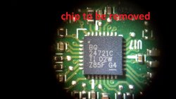
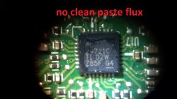
I am now trying to remove the 28 pin chip. with flux and my hot air station at 400 I can not seem to get it to flow the solder. Any ideas on that.

Sometimes I use this hook tip version but I find the heat right at the tip can be a problem and I have to use the "knee" to get more heat to a component. The hook is nice because you can angle it into tough spots.

http://www.all-spec.com/products/SSC-726A.html

Most of the time though I use this one. It is straight but seems to get a lot of heat to the tip.

http://www.all-spec.com/products/SSC-722A.html

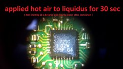
I run my hot air station at 500C and close to full air flow and a narrow tip only about twice the width of the chip itself. Takes about 30 seconds to get it hot enough to come off.

----------

Just to be clear, we are talking about pin 3 on D7005 being 4v not pin 3 on U7000 correct? Because it looks like you stated above that it should be 16v. I'm not sure if that was a mistake?

Sorry. I mean pin 3 on U7000. It should be 4V.
 
Sorry. I mean pin 3 on U7000. It should be 4V.

Oh ok, I also checked that before I left work just in case. It was 0v with just the magsafe connected.

So does this mean U7000 needs to be replaced considering we tested the D7005 and resistors seem to be good?
 
The attached .smc file is a sample from "SMC firmware updates for Intel-based Macs" (http://support.apple.com/kb/ht1237)

This coded file is flashed to the smc chip (-LoadApp option on smcf.c)

Any1 as found a way to backup the smc firmware b4 flashing it?

The problem for some mac models is that apple doesnt provide a .smc file - meaning u can't recover from a bad flash.

The bypass does work but is not the best solution 4 this problem.

I'm a hardware guy so this may be a dumb question but how exactly do you run smc.c? It seems that it is written in C so I guess you need to compile it into an executable?

I have a 2010 MBP13" that will not recognize the SATA hardware. I can boot off USB or SD Card. Apple Update says it needs the latest EFI firmware update. I wanted to flash the EFI and the SMC but when I run EFI flash utility it "says" it installs it and reboots but it never does do the proper update procedure on restarting (flashing sleep LED, Beep, progress bar). I am guessing it is because I am booting from USB. I was hoping to find a way to manually flash the EFI and SMC to see if this is just a firmware corruption issue. Can't see anything obvious wrong with the hardware.

If you could provide a step by step "for dummies" on how to manually flash SMC from the command line that would be greatly appreciated.

----------

Oh ok, I also checked that before I left work just in case. It was 0v with just the magsafe connected.

So does this mean U7000 needs to be replaced considering we tested the D7005 and resistors seem to be good?

Sounds like U7000 needs replacement then. Not surprised. I have replaced a lot of them. It is a bit of a tricky soldering job but if you have the experience soldering QFN packages it should not be a problem.
 
Sounds like U7000 needs replacement then. Not surprised. I have replaced a lot of them. It is a bit of a tricky soldering job but if you have the experience soldering QFN packages it should not be a problem.


I don't have much soldering experience when it comes to SMC to be honest. I've watched a bunch of videos but I mostly work on laptops replacing DC jack , reflowing GPU's, replacing through whole caps etc. I have all the equipment stereo microscope, hot air station , preheater, ultrasonic board cleaner..

Would you suggest desoldering and resoldering the U7000 both with hot air?
 
Check pins 4 and 6 on the battery connector. Those are the i2c communications from the battery to the charger and SMC. With system running they should be 3.4V. If not then you have a problem on that bus and SMC will not recognize battery -> will not start from battery.

Both of the pins have 3.4v and while the system is running, the battery is recognized, charged and it also works on battery.
Also, the 3.4v is always present on those pins, even if the system is not running, but has power, battery or dc. Could it be a problem with some pull-ups in the battery-powered circuit?

Any ideas?
 
Last edited:
I don't have much soldering experience when it comes to SMC to be honest. I've watched a bunch of videos but I mostly work on laptops replacing DC jack , reflowing GPU's, replacing through whole caps etc. I have all the equipment stereo microscope, hot air station , preheater, ultrasonic board cleaner..

Would you suggest desoldering and resoldering the U7000 both with hot air?

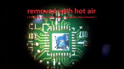
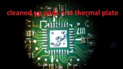
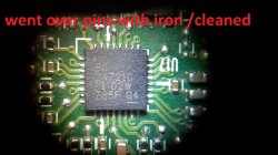
Use hot air to remove the old part. Then clean up the solder pads and the centre thermal pad. Leave a bit of solder on the thermal pad to ensure it solders to the package. Use liquid flux on the area and then place the new device carefully on the pads. I angle it up to view the side pads under the microscope and ensure all pins are aligned right. Then I hold it down with my tweezers and apply hot air 500C at medium airflow. Make sure chip does not move. If it does, try and nudge it back to centre. Once solder flows and chip sticks to thermal pad remove the heat. I then go around all the connections with soldering iron and make sure solder is flowed onto all connections. Laborious work but necessary. Don't just rely on the hot air tool to have soldered all the connections.

----------

Both of the pins have 3.4v and while the system is running, the battery is recognized, charged and it also works on battery.
Also, the 3.4v is always present on those pins, even if the system is not running, but has power, battery or dc. Could it be a problem with some pull-ups in the battery-powered circuit?

Any ideas?

That is correct. As long as the system has power from some source then G3Hot is on and those i2c busses are pulled up to 3.4V. Sounds like your pullups are OK. Whether the SMC/Battery/Charger are properly communicating is a more difficult thing to assess without a scope to see the communications.
 
Use hot air to remove the old part. Then clean up the solder pads and the centre thermal pad. Leave a bit of solder on the thermal pad to ensure it solders to the package. Use liquid flux on the area and then place the new device carefully on the pads. I angle it up to view the side pads under the microscope and ensure all pins are aligned right. Then I hold it down with my tweezers and apply hot air 500C at medium airflow. Make sure chip does not move. If it does, try and nudge it back to centre. Once solder flows and chip sticks to thermal pad remove the heat. I then go around all the connections with soldering iron and make sure solder is flowed onto all connections. Laborious work but necessary. Don't just rely on the hot air tool to have soldered all the connections.
.


Ok, I spent my day off in the shop practicing. This was my first QFN package but I think I did ok. The chip looks like it may have been slightly further to the left.
 

Attachments

  • 2013-07-04_16-12-49_619.jpg
    2013-07-04_16-12-49_619.jpg
    331.3 KB · Views: 307
  • 2013-07-04_16-14-58_766.jpg
    2013-07-04_16-14-58_766.jpg
    287.4 KB · Views: 340
  • 2013-07-04_16-17-29_160.jpg
    2013-07-04_16-17-29_160.jpg
    295.8 KB · Views: 250
  • 2013-07-04_16-26-35_74.jpg
    2013-07-04_16-26-35_74.jpg
    305.6 KB · Views: 234
  • 2013-07-04_16-45-27_422.jpg
    2013-07-04_16-45-27_422.jpg
    305.6 KB · Views: 242
I have a 2010 MBP13" that will not recognize the SATA hardware. I can boot off USB or SD Card. Apple Update says it needs the latest EFI firmware update. I wanted to flash the EFI and the SMC but when I run EFI flash utility it "says" it installs it and reboots but it never does do the proper update procedure on restarting (flashing sleep LED, Beep, progress bar). I am guessing it is because I am booting from USB. I was hoping to find a way to manually flash the EFI and SMC to see if this is just a firmware corruption issue. Can't see anything obvious wrong with the hardware.


The install procedure for people who cant use a hard disk and need to update their efi or smc firmware:

- Format a usb pen drive (GPT format with 1 fat32 partition)
- Extract from Apple smc & firmware update site your .smc and (.fd or .scap) firmware files. Also copy the EFIUpdaterApp.efi and SmcFlasher.efi to the usb pen.
- Using Terminal in macos x type:
login root
ls /Volumes (check your pen_name is listed there)
cd /Volumes/pen_name
bless -mount ./ -firmware EFIUpdaterApp.efi -payload MB_yourfile.fd -options "-x efi-apple-payload0-data" (the "./" means u'll use your usb pen to flash - dont need a real hard disk ;)

Reboot. if the flash fail u'll need to use Refind shell todo it. Log to refind shell and type:
map (check fs0 fs1 4 "usb" on the string)
fs1:
ls (should list your usbpen and files)

To flash the firmware u can type:
EFIUpdaterApp -x efi-apple-payload0-data

If you get a fast reboot it means the flash failed. To downgrade the firmware u'll need a hacked EFIUpdaterApp.
Otherwise u need to make your smc tobe in a speciall way so u can flash:
- Power off and Remove batery.
- old the power buton and plug the power cord. when you see the power led green release and old the power button.
- when the front led start to flash remove the power cord.
- redo until u figure out how it works ;)

boot to the usb_pen redo the shell commands. it should work

To flash the smc type SmcFlasher -LoadApp yourfile.smc

you can try to use the attached file to check 4 firmware status. type spiutil2 without any option. if you see a warning msg saying "flash restrictions apply" redo the power trick until the warn goes away.
 

Attachments

  • spiutil2.zip
    18.4 KB · Views: 224
Looks good. Much nicer to work on those green PCB's rather than the black PCB's that Apple uses :)

That's what I'm afraid of! unfortunately I don't have any apple boards to practice on. My hot air gun only goes up to 480c but depending on the distance of the wand I'm sure I can get it up to temp.


Few questions

- Do the Black PCB's have more layers in turn making it harder to preheat?

- Does apple use leaded or lead free solder? I'm assuming they use lead free if your recommending 500c to remove the chip or are you just using wand distance to control the heat?

- I cant seem to find the U7000 i6259AHRTZ (F025XR) on digikey.com do they sell it?
 
Last edited:
820-2915-B won't power on

Hi guys,

I have a small problem here. Two days ago I purchased a faulty Macbook Pro 15" core i7. Based on case damages I believe this laptop was dropped by previous owner, so now machine doesn't turn on but I get amber light when magsafe is connected. I have measured voltage in some places and found out, that PPBUS_G3H rail provides only 0.35 V (should be around 12 V right ?) The chip itself (U7000) does not look to be damaged. What would be next steps to diagnose, what's causing this issue?

Please have a look on some pics here as well:
https://www.dropbox.com/sh/y1hcblnopjd7eag/bu9L1WERss/820-2915-B

Thanks in advance.
 
That is correct. As long as the system has power from some source then G3Hot is on and those i2c busses are pulled up to 3.4V. Sounds like your pullups are OK. Whether the SMC/Battery/Charger are properly communicating is a more difficult thing to assess without a scope to see the communications.

Im thinking, what is different, when starting from battery vs. dc.
This is the only region that actually had liquid (made with crappy phone camera);
IMG_0553.JPG


If anyone can help, i also have the boardview file and schematics for this logicboard.
 
That's what I'm afraid of! unfortunately I don't have any apple boards to practice on. My hot air gun only goes up to 480c but depending on the distance of the wand I'm sure I can get it up to temp.


Few questions

- Do the Black PCB's have more layers in turn making it harder to preheat?

- Does apple use leaded or lead free solder? I'm assuming they use lead free if your recommending 500c to remove the chip or are you just using wand distance to control the heat?

- I cant seem to find the U7000 i6259AHRTZ (F025XR) on digikey.com do they sell it?

I think that the Apple PCB's have 8 layers. [edit] The MBP13 has 12 layers. There is a page on the schematics that shows the stackup.

Apple, as well as pretty much every consumer electronics company, uses lead free solder. RoHS requirements have pretty much ruled out leaded solder except for equipment that can use specific exemptions. Lead Free Solder has a higher melting point.

Last time I bought 6259's it was on eBay. I think I had trouble finding them at traditional sources.

----------

Im thinking, what is different, when starting from battery vs. dc.
This is the only region that actually had liquid (made with crappy phone camera);
Image

If anyone can help, i also have the boardview file and schematics for this logicboard.

That is the SMC. Corrosion around that can lead to all sorts of fun issues since most of the i2c busses are communicating to/from that device. Any of those get messed up and you can have a variety of issues. Clean the area carefully and examine under a microscope for corroded devices or vias. Sometimes a solder reflow on the SMC itself can help if liquid has seeped under the SMC.

[edit] To answer your question, the SMC is in control of telling the system to boot. If it does not sense the battery or DCin (or both) it does not matter if they are present or not. The SMC will not allow booting. Unless you use the SMC bypass of course.
 
Last edited:
I think that the Apple PCB's have 8 layers. [edit] The MBP13 has 12 layers. There is a page on the schematics that shows the stackup.

Apple, as well as pretty much every consumer electronics company, uses lead free solder. RoHS requirements have pretty much ruled out leaded solder except for equipment that can use specific exemptions. Lead Free Solder has a higher melting point.

Last time I bought 6259's it was on eBay. I think I had trouble finding them at traditional sources.

Does the (F025XR) after the i6259AHRTZ matter? I see them here on ebay http://www.ebay.com/itm/1x-NEW-ISL6259AHRTZ-ISL-6259-AHRTZ-QFN-28pin-Power-IC-Chip-Ship-From-USA-/230698892768?pt=LH_DefaultDomain_0&hash=item35b6b9bde0 but the chip says i6259AHRTZ (F014QL) not i6259AHRTZ (F025XR).
 
Pin 1 CHRG_AGATE has to put out 0V in order to turn on the FET. Your other voltages look good so it would seem that U7000 is bad.

You could check R7085 and R7086 resistance to make sure they are ok but I think pin 1 should be able to pull down to 0V anyway.

Ok, I know what is wrong with it, two shorts to GND:
- SMBUS_SMC_BSA_SCL (battery connector Pin 4, U7000 Pin 11, U4900 (SMC) Pin 100) 2.62 ohm
- SMBUS_SMC_BSA_SDA (battery connector Pin 6, U7000 Pin 10, U4900 (SMC) Pin 101) 12.2 ohm

Caps C6952,C6953 and D6950 (RCLAMP2402B) are ok. So what you reckon, which chip is more likely causing this short, U7000 or U4900 ??

Could be either one but U7000 is easier to change. I have never changed the SMC since it is a BGA. Some people on here have done it by just estimating placement and reflowing.
 
Also copy the EFIUpdaterApp.efi and SmcFlasher.efi to the usb pen.

I have searched and searched inside a variety of the EFI packages and can not find this EFIUpdaterApp.efi anywhere? I can find the .scap file no problem but not the utility. Where do you get that? I thought it would be embedded within the packages???

Thanks
 
MBP 13 booting but not charging

Finally received and replaced U6901. Now at least it's running. Thank you for all your help, just checking to see if you know all the Voltages around U6901
Here is what I have and need on U6901
1 Not Sure
2 Not sure
3 GND
4 3.25v
5 3.25v
If any one can help it would be greatly appreciated, It boots up fine works great, just will not charge. Dim green on Magsafe. 11.4 V on pins 1,2,3
3.4V on 4,6 0V 5 on battery connector.
 
Could be either one but U7000 is easier to change. I have never changed the SMC since it is a BGA. Some people on here have done it by just estimating placement and reflowing.
It's U7000 fault. Today, I used my work lab microscope and gently cut off pin 10 leaving soldering pad untouched.Now I'm getting 2.5k Ohm instead. Happy days.
 
Register on MacRumors! This sidebar will go away, and you'll see fewer ads.