Help with 2008 Aluminum Macbook
Hi Guys,
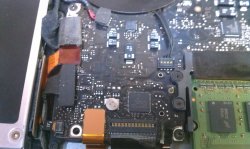
So I'm helping out a fellow with a 2008 Aluminum MacBook. The battery stopped showing up in the tool bar so the user bought a new battery. The new battery shows up and charges however when you disconnect the ac power it shuts off as if there is no battery. A SMC reset and Pram reset were done to no avail. Sometimes when the AC power is left in the green led will switch to orange then green back to orange flip flopping until a clean SMC reset is done. With SMC reset it will stay orange and charge battery. So far I have tested with a known good battery, DC Jack, Battery Indicator board with cable, and Battery cable and board all with no changes in results. Is there anything else that can be pointed out for me to test?
Hi Guys,
So I'm helping out a fellow with a 2008 Aluminum MacBook. The battery stopped showing up in the tool bar so the user bought a new battery. The new battery shows up and charges however when you disconnect the ac power it shuts off as if there is no battery. A SMC reset and Pram reset were done to no avail. Sometimes when the AC power is left in the green led will switch to orange then green back to orange flip flopping until a clean SMC reset is done. With SMC reset it will stay orange and charge battery. So far I have tested with a known good battery, DC Jack, Battery Indicator board with cable, and Battery cable and board all with no changes in results. Is there anything else that can be pointed out for me to test?