Become a MacRumors Supporter for $50/year with no ads, ability to filter front page stories, and private forums.
I doubt it is the DCin board if you are getting a green led. The behavior with wiggling the connector a bit is not too unusual. Th spring loaded pins may not be making proper contact so a little movement can suddenly engage them.

Re: G3Hot, it usually measures bang on 3.4V for me but it is possible that your meter is in error. Usually G3Hot either works or it doesn't. I can't remember seeing a case where it was putting out a slightly lower voltage. I think that the components that rely on it are probably forgiving of a slightly lower voltage.

Thanks for the reply. I should get myself a decent mm. I have a feeling this thing is stuck in sleep mode or the SMC is corrupt or something. Everything I have tested has came up fine up to now. I have seen a lot of these boards with no power up issue - I have yet to find the common fault that is at the bottom of it.

I'm not sure what to do next. It's almost like it needs a GPU reflow, but I'm not seeing this problem on late 2008 machines anywhere, so thought it best to check other things first and take that as a last resort.
 
Well I tried the long shot of replacing the MagSafe dc in board and as Dadioh suspected, it made no difference. Voltages across the board are the same. It won't go to waste and can be used in the future.

While I had the logic board out I checked voltages on that side and all seemed well, dc in fuse etc have normal voltages. I ran the tester over the tiny onboard battery and this gave a reading of 1.5v - Is this normal?

I have tried everything and it still won't power up. Where should I start looking next?

I don't believe that there is a battery. Can you post a picture of the device you are measuring? 1.5V is the voltage provided to the memory so you might be measuring a capacitor on the power output to that rail. I assume you are measuring voltages after trying to start the board? Is the fan spinning?
 
Hi

i know its a forum for MBP but my query is with MacbookAir(MBA).

but i have a MBA 2012 which had suffered liquid damage . .
clean it with isopropyl alcohol . .

The problem is the battery comes up with a cross when it boots.
The MBA boots up fine when connected to macsafe connector.

I tried the battery in a another MBA the battery works fine . . .
I also checked the white color fuse near the battery seems to be okay . . .

Need your help here guys to look for the faulty component on the logicboard . . .

I know its a forum for just MBP , if any one can redirect me to forum or thread like this for MBA would be appreciated or where i can start the debuging from.

thanks

The crossed out battery means that the SMC is not communicating with the battery. Probably one of the i2c lines is affected. If you can get a schematic for your model (you didn't say if it was 11" or 13"?) then find the page with the battery and look for the pair of i2C signals. They will have some pullup resistors on them. It is possible one of the pullups is bad.

If you are uncertain then post a screen shot of the battery connector from the battery and we can identify what to look for. You will probably need the boardview files as well as the schematic to search for the location of the pullup resistors.
 
I don't believe that there is a battery. Can you post a picture of the device you are measuring? 1.5V is the voltage provided to the memory so you might be measuring a capacitor on the power output to that rail. I assume you are measuring voltages after trying to start the board? Is the fan spinning?

I think you're right again. It measured 2.23V earlier when I tested it. It looks like a tiny watch battery lol

 
Hi Guys,

Still working on my 15" Early 2011 2915 and I think I have narrowed down the shut down during boot problem to a missing PPVCORE_S0_AXG supply. A good board gives me 0.4v immediately after switch on but not this one. Anyone have experience with this model? I believe this is the supply I'm measuring in the photo but cannot be sure without a boardview. Anyone know where to find the boardview for K91F Flying Dutchman (820-2915-A)?
21entzt.jpg
[/IMG]
 
I don't believe that there is a battery. Can you post a picture of the device you are measuring? 1.5V is the voltage provided to the memory so you might be measuring a capacitor on the power output to that rail. I assume you are measuring voltages after trying to start the board? Is the fan spinning?

Dadioh, I got the logic board to power up with fans spinning for the first time today. I removed the logic board, isolated the dc-in board with electrical tape to protect it from coming into contact with the logic board. Firstly, after reading some posts from earlier in the thread I temporarily shorted SMC_RESET_L (pin1 on U5000) with TP_SMC_RSTGATE_L (pin13 on U4900) with no power attached. I then attached the MagSafe adapter and shorted the live G3Hot pad to ground and the fans started spinning! After carefully reassembling everything I have not been able to replicate this. It does the same as before - Won't power up at all by any method, SMC bypass, SMC reset, G3hot shorting, pin 5 on keyboard connector.

At least the board powered up. It seems there may be a glimmer of hope for it yet? Does this give you any idea as to what the problem may be?
 
I found the 99% ISO

Where can you find 98% iso? Here I can only find 91%, good but not perfect. Did you special order it?

Hey astroboy I found that ISO you were looking for. Stumbled across it looking for tinning flux. Let me know if this helps. I think I still have the invoice, if you need the company name.
 

Attachments

  • image.jpg
    image.jpg
    1.3 MB · Views: 227
I think my problem is the SMC. I may try a hot air reflow. What is the melting temp for the BGA balls under the SMC?
 
Clean BGA chips?

I think my problem is the SMC. I may try a hot air reflow. What is the melting temp for the BGA balls under the SMC?

I'm also suspecting problems with my SMC. I've read a lot of the posts in this thread and it was very usefull until now. I'm only missing the boardview a lot, but those are probably not easy to get.
I'm working on my early 2011 i7 MBP 13", it has had an encouter with a misplaced cup of Senseo coffee... The coffee got in through the openings on the backside.
The damage is not that severe, the area affected is mostly on the underside of the MLB, some components are coroded and i'm waiting to use a microscore to see the damage up close.
I have cleaned the board with alcohol but i think the SMC got soaked with coffee :( It's right on the edge of the board where the coffee entered the macbook and because it is BGA type i suspect i have some problems i can't really see or clean.
My G3HOT is below 1 volt, SMC bypass doesnt work and my magsafe light remains off, also tested with new DC-IN board.
Does anyone have tips on how 'clean' the BGA under the SMC chip, or is desoldering, reballing, resoldering the only way to go? Or could i try reflow?

In the past I got a 2007 MacBook Pro with nvidia GPU chip. Somehow coke managed to get under the GPU. I shaped a square of blutac around the GPU and filled it with a pool of 98% ISO and let it stand for a while! I then emptied it, and flushed it out with ISO in a syringe pressing the plunger quite hard to get some pressure under the chip. It took a while and quite a bit of ISO, but I noticed it started to run free. To ensure it was dry under the chip I set my hot air to low heat (100c) to evaporate everything from underneath the chip. I had cleaned the mainboard of coke with ISO and a toothbrush prior to doing the GPU. Re-assembled and it came to life with no problems thereafter.

I wouldn't apply power to the board again until it's all 100% cleaned up as this will only add to the damage. Give it a good intensive clean, only then, when you're satisfied it's clean and dry, apply power and check G3Hot etc again.

Try what I done with the GPU on the SMC. It will obviously be harder to flush that tiny sucker out though but it's worth a shot.

I'm still wading through schematics for this late 2008 MacBook Pro I'm trying to fix. I'm learning a lot along the way. Although I suspect the SMC is the culprit, I'm still holding out on reflowing it, as the connector nearby has plastic edges and the last thing I want to do is melt it. When and if I do reflow the SMC I will make a template around the SMC to protect the outer components as much as I can.

I will probably use the same temp profile as I use to reflow GPU's on the SMC, as it's bound to be the same BGA lead free balls, only smaller so I'll shorten the temp duration, but bring it up to a temp I know works.
 
Fixed! It was a resistor. After learning my way through the schematics I narrowed it down to a memory channel related resistor! Took the plunge and replaced it after buying a 10x loupe and some high quality tweezers. This is my first component level logic board repair. My only experience before this was resoldering dc in jacks on pc's. Never have I worked to this tiny level before. In a relatively short time, I have taught myself some basic electronic skills, and SMT soldering. I am hungry for more, I just wish I'd started earlier in life. I have just bought a dead logic board to practice further.

It's so much fun! Diagnoses is like doing a jigsaw puzzle of a giant plate of beans lol :D

Although the 10x loupe served its purpose, I think I would have had an easier time with a stereo zoom microscope.

Welcome to the wonderful world of logic board repair. Very satisfying to sleuth your way through a repair. A boom style stereo microscope does make soldering small components much easier. If you do get one add on a 0.5X Barlow lens to give yourself more room to work between the microscope and the board.

Congrats :D

Thanks for the info. I am looking into them now. The ones I have found seem to have enough room to work on the outer edges of the board. I may try to find a second hand body and harvest a boom off something.

I just found a couple of problems. The wifi is sometimes switched off on boot up and won't switch on, when it does boot with it on its fine, and the trackpad buttons don't seem to work at all. Although the trackpad works fine.
 
Fixed! It was a resistor. After learning my way through the schematics I narrowed it down to a memory channel related resistor! Took the plunge and replaced it after buying a 10x loupe and some high quality tweezers. This is my first component level logic board repair. My only experience before this was resoldering dc in jacks on pc's. Never have I worked to this tiny level before. In a relatively short time, I have taught myself some basic electronic skills, and SMT soldering. I am hungry for more, I just wish I'd started earlier in life. I have just bought a dead logic board to practice further.

It's so much fun! Diagnoses is like doing a jigsaw puzzle of a giant plate of beans lol :D

Although the 10x loupe served its purpose, I think I would have had an easier time with a stereo zoom microscope.

Awesome! I'm still eager for that moment!
I am used to reading schematics, but i'm really having a hard time locating components without a board layout view :/
 
Hi, I wonder if anyone out there can help me. I am after the boardview of a 820-2850-A logic board. I believe it is a K18. I have 3 boards here to fix and have managed to find a schematic but due to the difficult nature of the fault, I need the use of the boardview for this board to help me further. I have looked in all the usual places and have only managed to find once place that has it, which is on a polish repair forum but you have to have a certain amount of credits to download the file. I have tried sites that sell schematics but they don't have the boardview for the K18.

Do any of you know other than the polish forum where I maybe be able to find the boardview. I don't mind having to pay for it from any of the schematic selling sites but I cant find one that sells it.

Any help would be greatly appreciated.


It's been a while. But here:
The K18 st a 820-2330 A
820-2350 is the K24 board.
I have both. If still needed, please use PM.


Es ist schon eine Weile her. Aber hier:
Das K18 st ein 820-2330-A
820-2350 ist das K24-Board.
Ich habe beide. Wenn noch Bedarf, bitte über PM.
dieett
 
Hello guys! (and sorry for my English again)

Today my "'problem" is a A1278 mid-2009 MacBook pro (13", core 2 duo 2,53Ghz)
Liquid damaged, and stocked 1 year in a room...

So i clean oxydation with alcohool, changing thermal paste, tring to boot with only logicboard, magsafe board and battery. Magsafe show me green and after orange! Great!
Keyboard no responding, like powerpads..

I replace all elements in the bottom case, still the same! no boot, but light on the left side showing charge is going on.

After 3 others cleaning, with only logicboard, fan and magsafeboard, when plugging the adapter, fan is spinning full rpm! GREAT!! I replace it to the mac, still the same.
when plug the magsafe, fan is going full power, led on the front is still lighting, no shime, no charge, no image/backlight.

The only way to shutdown the mac is to shortcut powerpads, power down directly.

By the way i leave the mac on my office, charging. When i come back, light was on front of the mac, fan spinning slowly, heat near processeurs... but nothing else. i try apple-D and apple-S, then i got the BONG, light goes on on the screen, earing the superdrive, GREAT!

No harddrive in it so it showing a interrogative folder.

Only way to shut it down is shortcut powerpads again.

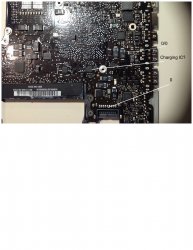
So my problem is powerpads have a strange comportment.

When i try to power the mac with them, the only thing is the magsafe light turn orange to green. After 5 sec it charge again (orange). When there is no battery plugged in, magsafe light is green stable but when i trying to boot, light goes off. like a shortcut somewhere, but no boot, only magsafe detection.
It's like a general reset. But when the mac is going on nicely, shortcut powerpads shutdown it nicely. Only way to make it alive again is to plug magsafe power, then it boot, charge etc.

Problem is strange, because with the BONG at startup and screen light i got no problem, work like a charm. Shotcutting powerpads to shutdown the board is right however. Only porblem is when i try to power the board with pads, nothing happend and i can't put it back to life with magsafe. So my board is in a state that it only charge, no boot. It work because i saw it.
Replacing keyboard can make difference? A way to power the board differently?

Thanks a lot, this Thread is marvelous and a weel of information!:)
 
820-2936-b power on bypass location?

Hello all,
I have a 2011 MBP 13" mc700ll/a 820-2936-b, with no response to the power button being pressed. G3hot 3.1v on one pad. If I attempt the G3hot bypass there is not response. I also tried the 5th and 29th pin on the keyboard strip, with no response. There is power on other locations of the board, the charging circuit is working comparing power levels with a previous posting. My question is, Am I using the right power button bypass method? Is there another way to test the power button without ripping it apart? Thanks on advance.

If you have a green or orange light at the MagSafe,and you have tried jumping the G3HOT pads and the keyboard pin 5 to ground then you certainly have a component failure. You will need to have schematics for your logic board and test extensively. The SMC is seeing something bad and not allowing you to power up the system. You have a long road of testing ahead of you. My problem was similar and it ended up being a memory channel resistor. But to be honest, it took a lot of work to find it.
 
Schematics link for 820-2936-b?

If you have a green or orange light at the MagSafe,and you have tried jumping the G3HOT pads and the keyboard pin 5 to ground then you certainly have a component failure. You will need to have schematics for your logic board and test extensively. The SMC is seeing something bad and not allowing you to power up the system. You have a long road of testing ahead of you. My problem was similar and it ended up being a memory channel resistor. But to be honest, it took a lot of work to find it.

Yes, I am getting a green then orange MagSafe lite. I found tremendous help in diagnosing a charging circuit and a needed reflow using a pic posted on this board showing most voltage readings for various points on the logic board. I think it was for a 820-2530-a 2.26ghz board.
I will have to research how to test the memory channel resistors, I am new to the component level replacement of parts.
Is there any place to find a picture of this board 820-2936-b 2.3ghz mc700ll/a? Pointing out voltage points across the board? Or a schematic of the same? But I prefer both, the picture giving me direction to general voltage readings on the logic boards seem to get me to the problem area. Thank you.

The problem you have could be anything. You won't know until you test via schematic - you'll need to weed your way through a google search to acquire the relevant files. The schematic will give you the needed voltage and component value/tolerance info. However you have to be lucky that the problem is something you can diagnose with the tools you have available. Some components need an oscilloscope etc for testing. Caps really need a specific tester also. I was fortunate that I was able to diagnose to the fault with a basic multimeter. You have the problem also of testing resistors 'in circuit'. I think your next step should be getting the schematic for your board along with board view. Then spend days, as I did learning your way around. It may feel like a chore but what you learn from this you will carry on this experience to other logic boards. I have just completed my 3rd logic board component repair and I'm streets ahead of where I was with the first one. What I have found is that unibody logic boards are surprisingly similar in their layout, even if there are 30 something different revisions. YouTube is a good place to look for mainboard diagnostics too. Good luck with it.
 
Hi, I wonder if anyone out there can help me. I am after the boardview of a 820-2850-A logic board. I believe it is a K18. I have 3 boards here to fix and have managed to find a schematic but due to the difficult nature of the fault, I need the use of the boardview for this board to help me further. I have looked in all the usual places and have only managed to find once place that has it, which is on a polish repair forum but you have to have a certain amount of credits to download the file. I have tried sites that sell schematics but they don't have the boardview for the K18.

Do any of you know other than the polish forum where I maybe be able to find the boardview. I don't mind having to pay for it from any of the schematic selling sites but I cant find one that sells it.

Any help would be greatly appreciated.


It's been a while. But here:
The K18 st a 820-2330 A
820-2350 is the K24 board.
I have both. If still needed, please use PM.


Es ist schon eine Weile her. Aber hier:
Das K18 st ein 820-2330-A
820-2350 ist das K24-Board.
Ich habe beide. Wenn noch Bedarf, bitte über PM.
dieett

Thanks for the offer but I have it now. many thanks

Rog
 
2009 13" MBP 820-2530 not charging battery?

Hi,
This 2009 MBP 13 works perfect after a spill and clean up.
all except it's not charging or seeing the battery. Smc reset, pram reset, known good battery, known good dc adapter. Battery test button shows no lites.
Checking a comparison board I noticed these two smd in the picture Reading 0v.
6th solder tab from ram chip on battery connector reads 0v.

Before I desolder and replace these two, can anyone let me know what there values should be? And if they are part of the charging system?
Thanks in advance
 

Attachments

  • image.jpg
    image.jpg
    482.8 KB · Views: 519
Register on MacRumors! This sidebar will go away, and you'll see fewer ads.