Become a MacRumors Supporter for $50/year with no ads, ability to filter front page stories, and private forums.
Hi Rpg16,

Is your meter digital or analogue? Analogue meters have a have a much lower input impedance than digital and could be dragging the voltage you are trying to measure down. The voltage on pin 3 must be above 3.2v for the charger to be happy (and set pin 14 high) so you need to be able to measure it. Also check R7010 and R7011, R7010 may have gone high in value. Pin 5 on the battery is the enable signal for it to set its output on - it should be low (it is pulled to ground via a 10k resistor).

Regards,
Chigwelldave.

----------


Hi canzil,

I did not receive my late 2011 this week so I can't be sure. I wonder if Apple has changed the part, as the EMC1414 is definitely 10 pin and the fitted component is 8 pin. That is going to make identification tricky unless there is enough information on the chip itself (when I get to see it). Does anyone know part numbers for other temperature sensors which have been used?

Regards,

Chigwelldave.

No problem mate, I sit down here and wait you get the late 2011 to identify this :D
Thanks for all
 
MacBook pro A1286 15 2.53GHz no clarion

Hi Everybody,

I've a macbook pro 15" (part number of the logic board: 820-2532-a).
It turns on, but I doesn't hear the apple chime, the screen displays nothing and the sleep led is lighting continously. (First I tried the SMC, PRAM reset..)
Then I thought that it was a problem of the GPU or memory of the GPU. I heated these, but it wasn't fixed. Next I flashed the SPI flash to a new bios dump, but the logic board didn't boot. I tried to change the SMC, but it wasn't booting. Has Everybody any idea?

Thank you!


hello macelek01, it seems that I have the same problem!
before we get to that, I had to replace the mosfet PPVCORE_S0_CPU. were short and were immediately shut down the macbook pro 15.
Now come on, no clarion, after three seconds turns off the fan, and then starts again ...
I inspected the entire board, all voltages and currents are ok.
you have solved? I suspect that this is the cpu faulty
 
MBP Fan Starts then starts again SIL remains on...

Hello,

I have an MBP 13" 2010 A1278 (no known water damage) and Macbook 13" 2010 A1342 (water damage) that exhibits the following:

1. Charges the battery.
2. Pressing power button causes the fan to turn on.
3. The fan turns off after about 5 seconds.
4. After a pause of 2-3 seconds the san restarts.
5. Now the Sleep light remains on.
6. The behavior remains the same if I remove All ram (step 2-5 above).
7. Absence of RAM doesn't make it beep (seems POST is not completing?).
8. System never goes to disk or dvd.
9. Nothing on display ever (external or internal).

I have tried with or without keyboard (shorting here posts to turn it on) no improvement in behavior.

Anyone seen this behavior before? If so, can you point me to that?

Anyone with any ideas where I should start looking?

Many thanks!
 
in my opinion, the problem revolves around the cpu and its power!
what voltage do you have on PPVCORE_S0_CPU? the capacitors under the cpu ...
 
PP1V5_S3 missing on 820-2327-A

Hello, I have one board with this faulty, in PP1V5_S3 don´t saw anything, I think this voltage is make inside the U7300, is it correct?,please I need help, sorry for my english I´m from Spain
 
Last edited:
volley85palermo, were you addressing me? And do you think you are seeing the same problem as what I am seeing, where Fan starts then stops and then starts again with sil light remaining on? If so, I haven't checked the PPVCORE_S0_CPU value yet, but would check and let you know.

I wonder if someone has the board view of A1278 and/or A1342 so we can locate the parts on the board.

Thanks
 
No Boot

I didn’t read the whole thread, many people were talking about charging problems. Has anyone fixed a unibody that won’t boot with a good battery and 3.4 V hotspot?

My 2009 MacBook Pro unibody 13 inch motherboard number 820-2530-A won’t boot either. The G3Hot rail says 3.4 V. I tried the 2 pin bypass but it will not work. Tryed the SMC reset and that doesn't work.

The battery will run low after it sits for a couple months but if I plug in the charger it will charge it rate backup. The battery indicator light on the side works, charger works , but nothing else does. Power seems to be all across the board, but no power to the USB ports, fan or hard drive. Doesn’t even check the CD.

Any suggestions?

I have not taken the mainboard out to see if anything was spilled on it yet. The person I bought it from said it just stopped working about a month after she took it to the repair shop, to have a new hard drive installed. She said she didn’t spill anything on it and the inside looks very clean and new.
 
Many thanks to all good people here who have posted schematics, board layouts, images and explanations of the power circuit. I wouldn't be able to fix my friend's mac without your help.

This it to report how I did it, in case somebody runs into a similar problem.

In fact, I had two fix two separate problems, both caused by the same fault; more on that later.

Cause: water spill; running wet for two days

Symptoms seen at various stages:

  • Machine turning itself on and off spontaneously
  • Battery not changing
  • Battery not recognised
  • Can only start from battery
  • With battery depleted, can only start with battery connector unplugged
  • Original MagSafe plug blown
  • Replacement MagSafe not turning its light on (light is visible, but dim)
  • Charger not recognised
  • Signs of corrosion on the logic board
  • No damage to keyboard or power button

Culprit: corroded via to pin 5 of U6901 (=PP3V42_G3H_ONEWIRE)

Ancillary problem: battery inoperative due to deep discharge

Hardware: MacBook Pro A1278 13" 2.26GHz K24 BETTER (the best ID I have)

Schematics: A1278-820-2879.pdf (not an exact match, but close)

Board layout: "A1278 820-2530 K24.brd" (posted here; the board file inside this archive needs to be renamed to drop the .zip suffix)

Back story: My friend toppled a glass of tap water near her mac, with some water splashing on the screen. She wiped the screen and forgot about the incident. Said no water had been seen on the keyboard. Later on the same day, her mac turned itself off while she was working on it. After a while, it did so again. Having now linked this new behaviour to the water spill, she decided to leave the machine turned off until the following Monday, with the view to ask me to look into it. An hour later, the machine turned itself on. Now seriously concerned, my friend decided that saving her data from the errant mac was of greater urgency. She spent the following two days fighting it.

Investigation:

  • When I first saw the damaged machine, it was turned on and still appeared to be functional, except the battery was fully depleted and "Not charging" was showing in the battery indicator.
  • I took it apart and examined the damage. There was still liquid water on the bottom cover under the power circuit, and some parts were soaked in water. Part of the board was covered with white residue, showing copper-blue around some large components such as electrolyte capacitors. Apparently, the water got in through the air intake on the right side of the body.
  • The keyboard appeared dry, but in view of the report of erratic power-on, I thought it wise to examine the power button. That dragged me into an unwarranted quagmire, but at least I can say I know how the power button is made. (An unfortunate casualty of that endeavour is keyboard lighting. I failed to align the light guide and now only the middle two columns are illuminated. Seeing how fragile the keyboard was, we chose to continue without keyboard lighting)
  • Cleaning and drying the board presumably curtailed the damage but lead to no improvement.
  • The first attempt to run it from external power led to the destruction of the MagSafe adapter. Its light shined unusually bright, then became intermittent and died off. That adapter could no longer be used with this or any other mac and had to be retired.
  • With the new adapter plugged in, the machine would not start.
  • Without external power, the machine could only start while there was still some energy in the battery. Because it was depleted beyond the safe limit, it would only run for a few seconds before shutting down.
  • Eventually, the battery went so dead it could not start the machine.
  • After much fiddling, I found that the machine was basically alive and could run from external power, but only with the battery disconnected. I did not know about the SMC bypass and did not know you guys existed (and google failed me), so I settled on this start-up procedure:
    • Connect external power
    • Plug the battery connector in (not 100% certain it was necessary but seemed to help)
    • Unplug the battery
    • Push power button and release after 3-5 seconds. Much shorter or much longer intervals did not seem to work

    This procedure worked most of the time, with a higher failure rate in the beginning, probably due to residual moisture in the board still interfering. Recently, it worked without failure. I judge it to be a better way of running a damaged mac because the SMC remains online and can be tested. Had I known about the SMC bypass, I could have missed some important information.
  • Connecting the battery while the machine was running resulted in an immediate power-off.

Repair

Having considered the above symptoms, I came to a tentative conclusion that there was irreversible damage in the logic board and decided to wait for a good deal on a replacement. Now, a whole year later, no such deal came about, and I was almost ready to send the board to a fellow in Taiwan (cf. "ebay logic board repair") who promised to fix it for $90 provided it was fixable. But I did not feel good about it, because it was going to cost a lot of money in any event (shipping and all), and I wasn't even sure what the problem was. So I gave it another look just to be able to describe it properly. First, I made quite a bit of progress by fixing the presumed-dead battery, and then I discovered this wonderful forum (which really needs to be digested to some usable form, by the way).

  • Battery
    Since there was apparently no way to charge the battery in situ, and buying a new battery just for testing seemed like an almost certain loss of money, I ripped the dead battery's housing open, cut the red and black wires inside and used them to connect it to a "dumb" 9.6V Ni-Cd power tool charger. The "dumb" charger does not monitor the battery, so you can use it any way you want. The initial current was 0.5A, and I left it running overnight. By mid-day next day, the current was about 0.2A, with the voltage drop across the battery close to 13V.

    Left to sit for several hours after charging, the battery showed no appreciable loss of voltage, and I thought it was up for a test. I put the cells back in what remained of their housing and taped it all together. (NB.: If I were to do it again, I would warm the battery with a heat gun or a hair dryer, or put it in an oven for a few minutes, to soften the adhesive that is used to attach the cells to the housing. It was relatively easy to crack the housing open -- which is best done when it is cold -- but taking it apart without first warming the adhesive can damage the housing and the cells. Also note that there is no extra space to accommodate any enlargement of the battery, so the final taping must be minimal. Use just a single layer of thin scotch tape over the parting line and one layer to cover the open part of the housing)

    Incredibly, the so treated battery worked fine. The machine was able to start with or without external power. The battery indicator reported "Not charging" and "Service battery", but while the former was a problem yet to be addressed, the latter was likely due to old age. The profiler informed:

    Health Information:
    Cycle Count: 819
    Condition: Check Battery
    Battery Installed: Yes
    Amperage (mA): 1.6
    Voltage (mV): 12206

    At any rate, at this point, the battery was talking to the SMC (which fact I could ascertain with a scope), and it even turned out that the "Not charging" message was a lie. After my rough-and-ready external charging, the charge level as seen with CoconutBattery was 89%; it went up to 100% a few hours later.

    I felt I could even leave it at that. The machine was fully functional, the battery was charging; it could sleep and wake up and was again a real laptop (as opposed to a crippled desktop it was year ago). But the SMC not talking to the charger and the MagSafe light not being operational represented a usability problem (however slight), so I pressed ahead with the charger and that was when I discovered this forum. I was amused to see somebody suggest jerry-rigging a charger for the battery in one of the first several posts; that was the first idea that came to my mind, but I'm not sure it would have worked with the smart interface this battery has, which shuts itself off when the charge gets depleted. BTW, I found the charge to be around 7V, evenly distributed among the cells, even after a year in storage, with only a few mV showing on the outside.

  • Charger circuit
    I soon found that the charger was working and therefore I did not need much of the priceless knowledge about the FET gates shared in this forum. But finding the remaining few bits about the charger sense signal took some digging.

    This was the condition I saw when I restored the battery and plugged it in:

    AC Charger Information:

    Connected: Yes
    ID: 0x0000
    Wattage (W): 0
    Revision: 0x0000
    Family: 0x0000
    Serial Number: 0x00000000
    Charging: No


    While no data was coming in, it was clearly there and working, so "Not charging" was blunt misinformation.

    The battery charger U7000 was happy, with its =CHGR_ACOK on pin 14 showing high.

    On first testing, the charger sense line appeared to be severed. It only seemed to be clamped by a diode to -0.2V, or maybe a Zener, but I did not reach the Zener breakdown, the way I tested it, so don't know which one it was. There appears to be a Zener diode on the DCIN board. I tested the line with the ambient field by keeping my finger on the tip of my scope's probe. It went up all the way, but hit the floor at -0.2V. Past the diode, it felt like it wasn't connected to anything. The DC resistance in each direction was several megohms, which could be just dirt. No DC at all was to be seen where wise people tell me I should expect 3.4V.

    It took me a while to determine that my "1-Wire OverVoltage Protection" circuit was entirely packaged in a single IC (the relevant schematics cited above can be found in a couple places in this thread, but they differ from the most-discussed version and are not easy to find).

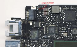
    While poking around this IC (U6900, MAX9940) and its gate (U6901), my probe fell through when I touched a test pad for =PP3V42_G3H_ONEWIRE (shown in the first picture). Looking at it through a microscope, I found that it had no metal in it; it was rust all the way in.

    View attachment 443969

    It turned out to be a via, with its opposite side still connected to C6908, where I did find the promised 3.42V. This line is apparently routed on the inner layer of the board and this via is the only point in this vicinity where it comes to the surface.

    To repair it, I first cleaned it out with a piece of 34-gauge steel wire. Copper did not work. All needles I had were too thick and promised to ruin whatever metal was still left on the good side of the via. Doing this under the microscope, even steel felt like a flaccid sausage. It positively did not want to stay in that hole, let alone go deeper in it. The copper wire I tried first felt like a squirt of toothpaste. It is amazing how the microscopic perception of these materials differs from our everyday experience with them. Later, trimming that steel wire with a utility knife felt like cutting through butter.

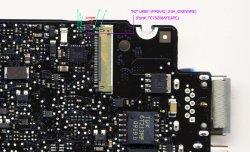
    Eventually, I was able to thread the steel wire through the via and clean all the detritus out of it. I soldered the same wire to the remaining part of the trace leading to U6901, and to the pad on the opposite side. The result is shown in the second picture (poorly -- my microscope is not instrumented, so I had to use a handheld camera).

    View attachment 443971

    That was all that needed to be fixed. The circuit that seemed to be severed (sing an ode to the FETs) came back to life and all is well now.

    I have also attached a couple pictures of the relevant part of the board. These may be helpful in further discussions of this particular layout.

    View attachment 443973
    View attachment 443974

I second to this troubleshoot that saved me a new logic board!!! BIG Thanks to tidewatcher with this priceless experience
My MBP 13" 2010 that has beer spilled on and took a dive, after washing the board let it dried just to find out it would only work with a battery, Magsafe isn't detected or charges, but instead shows very dim green light & dim flashing amber. I've been following this thread all along in silence with very limited knowledge of reading schematic, i've made various attempt to revive it by tracking current, checking burnt or missing components, replacing a couple parts still no luck until today after 3 days, looooong hours of reading & following this thread, guessing and some more cursing i've finally came down to this sucker "R2" 5-pin U6901 (PP3V42_G3H_ONEWIRE) (Part#: TC7SZ08AFEAPE) that its path to via point is corroded & broken, causing it unable to link to reverse side of this capacitor C6908, whereas U6900 (MAX9940) is next to it. Having to discover this disconnection i then try to test bridge it to capacitor C6908 using a thin wire and it works!!! U6901 pin# 5 shows 3.42V, which it's supposed to be and there goes the Magsafe green light lit up my room!!! :D and charges the battery right afterwards
So my fix is a little different than tidewatcher, instead of trimming, cutting and squeezing through a tiny hole i jump a thin wire to C6908, which i imagine save me sometime sweat with this
*** Sumary of my case:
-Beer spilled MacBook Pro 13 2010
-Only take battery but fully functional after washing the logic board
-Won't detect Magsafe, very dim green and amber flashing lights
-Power board shows split 14V & 2V, not 16.5V
-U7000 (ISL6259) (=CHGR_ACOK) pin-14 is fine @3.3V
-G3HOT is fine @ 3.42V

But i gotta admit, with my limited skills and experience, i couldn't have fixed it without this forum that full great people and bright ideas. I also got aid from a dead board for parts and another semi-working board for comparison as well besides soldering skills, 2 multimeters, microscope and a few cups of joe

Attachments of my fix
 

Attachments

  • ttt1.jpg
    ttt1.jpg
    276.5 KB · Views: 3,860
  • ttt2.jpg
    ttt2.jpg
    307.1 KB · Views: 3,444
Last edited:
volley85palermo, were you addressing me? And do you think you are seeing the same problem as what I am seeing, where Fan starts then stops and then starts again with sil light remaining on? If so, I haven't checked the PPVCORE_S0_CPU value yet, but would check and let you know.

I wonder if someone has the board view of A1278 and/or A1342 so we can locate the parts on the board.

Thanks

it seems we have the same problem ... I ordered new mosfet. I hope these are!
 
it seems we have the same problem ... I ordered new mosfet. I hope these are!

Volley85palmero thanks for your help.

Dadioh/cmdrdata, can you please advise as well?

Below is my observation:

Q7400

1. Pin 4 (Gate) = 34 V
2. Pin 5 = 12.5 V
3. Pin 1,2,3 1.1 V

Q7401

1. Pin 4 = 4.5 V
2. Pin 5 = 1.1 v

L7400

1. The pin that connects wtih Q7401 Pin 5 = 1.1 V
2. The other pin 1.0 V

I have also noticed that before fan goes high, the Pin 4 of Q7401 is at 20 V and 1,2,3 at 12.5 V But I wonder if Pin 4 of Q7401 (gate?) should never be more than 4.5 V?

Thanks,
 
I am having a look at the EMC 2326 820-2530-A MBP 13 board.

No G3HOT 3.42 on only battery operation at the jump points pictured way earlier in the thread.

Good 3.42 with normal startup, charging and normal operation on AC.

So I appear to be loosing the 3.42 on battery only power.

Earlier discussion points out this might be a problem with Q7055 and Q7056.

Are these their location on this board?

Thanks

This is Q7030 and Q7035
 
I’m getting 3.393 volts

Some are reporting 3.42 V on the G3HOT. I’m getting 3.393 volts on my Mac Pro 13 inch June 2009 model that won’t boot. I thought this might just be my RadioShack voltmeter.

If it has to be 3.42 V to start the laptop, I think I found my problem and need to back trace to find out where the voltage lost is.

Does anyone’s laptop start at less than 3.4 volts? Just wondering if it’s that Touchy.

Can anyone post a picture of the G3 hotspot on the early 2011 MacBook Pro 13 inch?

That one of mine boots and I can check my voltmeter to see how accurate it is.

Thanks.
 
please help me :(

macbook white 13 a1342

completely dead

only green light from magsafe

i'me dismantled it and it seems al clear and ok

what can i do?

please help me

sorry for my bad english!
 
No problem mate, I sit down here and wait you get the late 2011 to identify this :D
Thanks for all

Hi canzil,

I received my 13" late 2011 but it reveals no additional information. I can confirm the photo you have seen is correct, the part has E3 4B on it and it is a DFN8 device but there is no other information.

Sorry mate,

chigwelldave.
 
Hi canzil,

I received my 13" late 2011 but it reveals no additional information. I can confirm the photo you have seen is correct, the part has E3 4B on it and it is a DFN8 device but there is no other information.

Sorry mate,

chigwelldave.

Ohh thanks chigwelldave, but now I dont know what do, is there any way I can find out which part is? with the schematic or something?
 
Some are reporting 3.42 V on the G3HOT. I’m getting 3.393 volts on my Mac Pro 13 inch June 2009 model that won’t boot. I thought this might just be my RadioShack voltmeter.

If it has to be 3.42 V to start the laptop, I think I found my problem and need to back trace to find out where the voltage lost is.

Does anyone’s laptop start at less than 3.4 volts? Just wondering if it’s that Touchy.

Can anyone post a picture of the G3 hotspot on the early 2011 MacBook Pro 13 inch?

That one of mine boots and I can check my voltmeter to see how accurate it is.

Thanks.

Hi GoTimothy,

I've just repaired a 2010 13" MBP with no G3HOT - this now reads 3.395 volts and works fine. The tolerance is pretty wide on the G3HOT, the schematic for the 2009 states 3.31v minimum to be supplied to SMC reset chip. 3.393 should be plenty, the first supplies to come up on starting are the 'state 5' 3v3 and 0v9 - you should see if they come on as your next step.

Do you mean the debug power button or G3HOT test point when you say G3 Hotspot? You can get a rough measurement of G3HOT on battery pins 4 or 6 (battery comms pulled up to G3HOT).

Regards,

chigwelldave

----------

Ohh thanks chigwelldave, but now I dont know what do, is there any way I can find out which part is? with the schematic or something?

Hi canzil,

The schematic for the Early 2011 (I don't have a schematic for the late) states the device is an EMC1414-A but this part is 10 pin so something must have changed in production. I'm not sure how to find this out unless someone has a reference to SMD manufacturer's codes and can look it up. I've tried internet searches but come up with nothing.

Maybe it's worth trying to pull one off a scrap board and replacing it - this can be done with a hot-air soldering station but it's not easy.

Regards,

Chigwelldave.
 
Hi all. Thanks for all the great information on this thread.

I have an early 2011 MBP 15 that was a relatively “minor” liquid spill.

It is board # 820-2915-b. It is no boot, no video, no chime. Normal resets are no help.

The magsafe will charge the battery. The side light led’s will read the battery.

Currently when the magsafe is plugged in it will begin to spin the fans, light the sleep light, begin to power the drives, then shut them off, pause, and repeat .

The 3.4v is present and the I can start or stop the above looping procedure with the power on pads with the board out or the power button with the board in.

It acts the same with the board in or out and I currently have the board out on the bench.

I have the K91F Schematics but no board view.

Any thoughts or ideas in a troubleshooting direction would be appreciated.
 
more measurements and waiting on microscope

Hello again,
and much BIG THANKS to Dadioh the thread starter and original teacher here, and cmdrdata another very smart teacher. I first appeared here in mid July (page 74). I've gotten quite a bit of amazing info reading this entire thread over. For me especially paying attention to the discussions of mac-n-sauce, rufunky, as they were working on the same LB. Also really appreciated laptech's postings and explanations of successes. Would very much like to see a photo of the corrosion laptech referred to as something esp. to look out for on the LB.


Waiting on arrival of stereo microscope, and trying to decide which hot air/soldering rework station to get (probably the X-Tronic 4040. Spending all this $ means I'll have to fix/fool with more than the one I'm working on now, to justify the cash outlay; however, I do love puzzles so...

the liquid damaged LB has been cleaned a second time with 99% isopropyl. Maybe when I get the microscope I'll see something I've missed. Unable to boot with adapter, battery depleted. No go via shorting of the G3HOT, or by 5th pin of keyboard connector. Fan makes no movement whatsoever. The led on the adapter is dim and blinks.

Now for the real info: the LB is 820-7829 B

G3HOT = 3.37V on one, and 0V on other pad

fuse by battery connectionion both sides = 12.57V

ISL6259 U7000
Pin 14 = 2.32V
Pin 1 = .02V to .09V
Pin 24 = 16…V

Q7080 (top side) = 16.75
Pin 1 = 12.56V
Pin 2 = 12.56V
Pin 3 = 12.56V
Pin 4 = 5.80V

Q7085 (heatsink side) = 17.22V to 17.27V
Pin 1 = 16.74V
Pin 2 = 16.74V
Pin 3 = 16.74V
Pin 4 = 15.52V

Q7030 16.73V
Pin 1 = 13V to 13.12V
Pin 2 = 12.39V
Pin 3 = 12.33V
Pin 4 = 12.24V

Q7035 = 12.35V
Pin 1 = .54V
Pin 2 = 0V
Pin 3 = 0V
Pin 4 = 0V

i2c 10.89 Kohms on pin 4 and pin 6 to G3hot

5V 3.3V power output device (51125) 4 Caps and (small green "R010" a R or C?) all = 12.5V

When you look at the LB measurements, what is it saying to replace? Is it the ISL6259 U7000 because of the low reading on Pin 14 and Pin 1 NOT being at 0V? Q7080 looks good, but what about Q7085 Pin 4 reading? And then Q7035?

Advice and ideas appreciated. :D
 
hi im a newbie on this and I'm having problem with a macbook pro 1278,the magsafe turns green but the board doesn't respond i tried measuring some of the circuit and i don't get voltage on some of them, i wish could find all this part on the schematic but i don't have no idea where to start please help. thanks in advance.
 
'state 5' 3v3 and 0v9 -


Hi Chigwelldave,

3.393v On the test pins on the board that you’re supposed to short to boot up without hitting the on button. But now it reads 3.390v

“state 5' 3v3 and 0v9 - ” I’m a newbie, that’s too over my head. Can you explain better? I suppose your talking a place on the schematic ie P3v3SO_SS ect or a component? “state 5'” ?


But I also have the 13" early 2011 EMC 2419 that I can use schematics to fix the backlight if you know where I can find them.

Thanks for any help.

Found board view and schematics for 2009 need 2011
 
Last edited:
Hi Chigwelldave,

3.393v On the test pins on the board that you’re supposed to short to boot up without hitting the on button. But now it reads 3.390v

“state 5' 3v3 and 0v9 - ” I’m a newbie, that’s too over my head. Can you explain better? I suppose your talking a place on the schematic ie P3v3SO_SS ect or a component? “state 5'” ?


But I also have the 13" early 2011 EMC 2419 that I can use schematics to fix the backlight if you know where I can find them.

Thanks for any help.

Found board view and schematics for 2009 need 2011

Hi GoTimothy,

The 3v3 and 0v9 (actually 1.05v on the 2009) have components big enough to measure with a meter. You need to find L7770 for the 1.05v and L7220 for the 3.3v. Schematic K24, 820-2530 will help you along but you may need a board view to help you locate the components. I may be able to take a picture later if you need.

The 2011 may just be a fuse, check F9700 (3A 0603 package) just west of the LCD connector.

Regards,

Chigwelldave.
 
Hi GoTimothy,

I've just repaired a 2010 13" MBP with no G3HOT - this now reads 3.395 volts and works fine. The tolerance is pretty wide on the G3HOT, the schematic for the 2009 states 3.31v minimum to be supplied to SMC reset chip. 3.393 should be plenty, the first supplies to come up on starting are the 'state 5' 3v3 and 0v9 - you should see if they come on as your next step.

Do you mean the debug power button or G3HOT test point when you say G3 Hotspot? You can get a rough measurement of G3HOT on battery pins 4 or 6 (battery comms pulled up to G3HOT).

Regards,

chigwelldave

----------


Hi canzil,

The schematic for the Early 2011 (I don't have a schematic for the late) states the device is an EMC1414-A but this part is 10 pin so something must have changed in production. I'm not sure how to find this out unless someone has a reference to SMD manufacturer's codes and can look it up. I've tried internet searches but come up with nothing.

Maybe it's worth trying to pull one off a scrap board and replacing it - this can be done with a hot-air soldering station but it's not easy.

Regards,

Chigwelldave.

Hey friend, I search a lot on web and can find the schematic and .brd to my model. You can take a look on this for me?
A1278 k90i 820-2936
https://www.dropbox.com/sh/diev4xr4rddr0mh/G5ipvcy9RW
 
hi im a newbie on this and I'm having problem with a macbook pro 1278,the magsafe turns green but the board doesn't respond i tried measuring some of the circuit and i don't get voltage on some of them, i wish could find all this part on the schematic but i don't have no idea where to start please help. thanks in advance.

Hi sombie14,
in order for knowledgeable folks to help you they need more information. Which 1278 model do you have? 13" 2009, mid 2010? you can find more info on your LB, located on the sticker where the ram slots are, and or etched on your board. Unfortunately the Apple boards are black and the etched numbers hard to see, but they're there. On my LB the numbers (very tiny) are found on the edge of the board near where the keyboard connection is, on the side. Once you know which board you have then you look for the schematic for that board. My board is a 13" mid 2010 and the version # is 820-2879 B. @ this time, my understanding is that the version B is slightly different. I'm working off of the K6 schematic which I've attached, just in case that happens to be your LB also.

I'm new at this also; it's a matter of reading through some of the posts (especially the first few pages). Also you can use the "search this thread" option to look for posts relevant to your particular board and or problem voltage or resistance to see what others found out was wrong, or how they solved a problem. You need to figure out what to measure, and what the voltage or resistance should be. Good luck there is much to learn. I'm still slowly figuring out how to read/follow the schematic.
 

Attachments

  • A1278-820-2879.pdf
    1.4 MB · Views: 400
Last edited:
Hi all. Thanks for all the great information on this thread.

I have an early 2011 MBP 15 that was a relatively “minor” liquid spill.

It is board # 820-2915-b. It is no boot, no video, no chime. Normal resets are no help.

The magsafe will charge the battery. The side light led’s will read the battery.

Currently when the magsafe is plugged in it will begin to spin the fans, light the sleep light, begin to power the drives, then shut them off, pause, and repeat .

The 3.4v is present and the I can start or stop the above looping procedure with the power on pads with the board out or the power button with the board in.

It acts the same with the board in or out and I currently have the board out on the bench.

I have the K91F Schematics but no board view.

Any thoughts or ideas in a troubleshooting direction would be appreciated.

Hi, I have a board with a similar or same fault - power on, start to initialise optical drive then switches off and the cycle repeats. This was a liquid damaged board too. I have another with a video fault which will boot so I can take some measurements if you need. I have no heatsinks for these now so I can't power the boards up but I can do resistance checks if it'll help.

Chigwelldave.
 
Register on MacRumors! This sidebar will go away, and you'll see fewer ads.