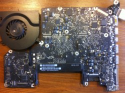
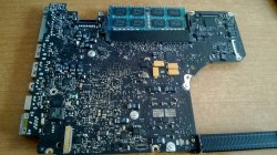
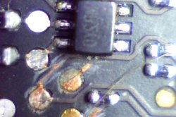
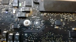
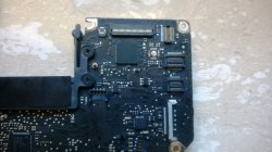
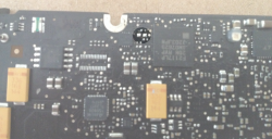
If anyone has the patience to teach me how to read semantics or (simply give me some tips) and the board view, let me know.
I figured out how to search for component locations, but cant figure out how open, short, work.
"Open" and "short" are idealisations invented by the impatient. They don't have a precise definition and are best thought of as outcomes of a test procedure that varies from one situation to another.
Let's start with "short". It means "a huge leak in the circuit we're testing". Now all we need is to define "huge". Let's say, you're testing a 5kV power circuit for a He-Ne laser, and your ohmmeter reads 1 megaohm. That's a short, because your power supply will lose 25W through that leak, provided it can cope with it. It probably can't. For the opposite extreme, consider the massive lead connecting one of your car's battery terminals to the body. You test it with your ohmmeter and it reads 0.01 ohm; (most meters will show it as 0). Is it a short circuit? It would be, from the battery's point of view, if you connected it across the battery's terminals. That would make for a huge leak. But in some cars, the voltage drop across the ground lead is used to sense the battery current, so it is not that short from the sensor's point of view.
In a typical logical circuit, if you measure resistance to ground or to the power bus, you will need to worry about a possible short if your meter shows less than 1k for a TTL circuit, and less than 10k for a CMOS circuit (Note: these are just rough rules of thumb. It can be 10k and 1M, respectively). Also, it will depend on whether you're testing a live circuit or not, and in what direction. I would be more suspicious of a short if I measured an unusually low resistance of a constant value in both directions. Having it low in both directions rules out semiconductor effects inside the devices connected to the circuit you're testing.
In other words, your ability to ascertain a short in a circuit depends on your knowledge of what to expect in that particular circuit. For a logic board like your Mac's, if you see zero to several ohms anywhere on a signal circuit, you can be sure it's a short. A few hundred ohms -- maybe, but you need to investigate whether it is supposed to be like that. Some circuits are driven with open-collector gates (or their CMOS equivalents) and may include a pull-up resistor that will give you that reading (a typical pull-up will be anywhere between a few hundred ohms and a hundred kiloohms). So a few kiloohms will appear like an unlikely short (but be more suspicious if it is symmetric and occurs where you expect to find really high impedance).
For detecting open circuits, you use similar kinds of rules, but you need to be even more aware of semiconductor effects. For an "open", always test in both directions. If you see "infinite" resistance in one direction, but some decidedly finite resistance (hundreds of ohms to kiloohms) in the opposite direction, you've hit a diode or a diode-like structure; possibly lots of them inside participating devices. So it is neither short nor open; it may be a functional signal circuit.
It is only open if it shows "infinity" in both directions, but be aware of normal leaks, because everything on this board -- capacitors and semiconductors -- will leak a bit. So "infinity" can start anywhere from, say, a hundred kiloohms to a hundred megaohms. A gigaohm will be a certified infinity for this type of board, but don't be pedantic: you can introduce a permanent leak on the order of tens of megaohms (or worse) just by touching the board with your fingers (so it's a good idea to wash your hands or put your lab gloves on when working with high-impedance circuits -- although your mac's logic board should not be that sensitive).
Also note, if while testing for an open circuit you see a resistance drifting upwards to infinity, you've probably hit a capacitor that is charging from your meter. If that's so, it will eventually settle at a very high value or will make your meter go out of range.
Finally, note that some semiconductor devices will test as open until you reach a certain breakdown voltage. Try testing an LED, for example. If your meter uses a low test voltage, it may appear like a regular diode, showing open circuit in the reverse direction. But it will show a finite resistance if you meter's test voltage is high enough to light up the LED. Conversely, if it is too low, even a regular diode will appear open in both directions. You need at least 1V to reliably test a diode.
Beware of CMOS gates that are very good at faking an open circuit when commanded open, at any voltage up to hundreds of volts. It may read open, but it does not mean it is faulty.
Some meters use special modes for testing diodes and short-circuits. I have a 20-year old RadioShack multimeter whose short-circuit mode has enough intelligence to give me a beep in most situations that I myself judge as short circuits on close examination. It is a very good first-approximation detector, but I always double-check its readings.
These are just a few things that come to mind -- just to show you why patience is required explaining what's short and what's open.


