Become a MacRumors Supporter for $50/year with no ads, ability to filter front page stories, and private forums.

nemo.

macrumors member
May 16, 2013
40
0
@cmdrdata

A while ago you mentioned a block diagram of U7000. Do you by chance know
which page in this thread it is located? I couldn't find it.

I'm currently facing the problem that the right side of R7086 on a k90i is
~15.5V instead of ~0V but CHGR_AGATE is at 0V. It might just be that pin 1
of U7000 is not soldered on correctly but I thought understanding the logic
could be beneficial.

My current understanding is that CHGR_AGATE will pull to zero when everything
is alright (U7000 has 5V at PP5V1_CHGR_VDD and reports SMC_BC_ACOK). Is that correct?
 

nemo.

macrumors member
May 16, 2013
40
0
Hi guys

I have here also a isseu

Its a logic board from a macbook pro 1278 with a 2,53Ghz i5 CPU

It had liqued damage.
After cleaning the board ,power for charging the battery is good and loads the battery(when its fully loaded the magsafe turns green)
also the indicator on the side says thats the battery is loaded.

But When i trying to start the macbook nothings happens.
I have also tryed the jumpers on the board its self(nothing)
G3hot is active 3,4V
One jumper gives 3,4 V and the ground is also good 0V
I have also changed the keyboard but the macbook won't start

Can sombody help me with tips(bypassing something)

sorry for my pore englisch (i live in the Netherlands)

Does SMC bypass or NVRAM clearing do any good?
Does the fan start spinning?

IIRC you should get at least 12V at F7040, can you confirm that?
 

cmdrdata

macrumors 6502
Jun 10, 2011
377
2
Dallas, Texas, USA
@cmdrdata

A while ago you mentioned a block diagram of U7000. Do you by chance know
which page in this thread it is located? I couldn't find it.

I'm currently facing the problem that the right side of R7086 on a k90i is
~15.5V instead of ~0V but CHGR_AGATE is at 0V. It might just be that pin 1
of U7000 is not soldered on correctly but I thought understanding the logic
could be beneficial.

My current understanding is that CHGR_AGATE will pull to zero when everything
is alright (U7000 has 5V at PP5V1_CHGR_VDD and reports SMC_BC_ACOK). Is that correct?

Attached is a pdf file for ISL9518. This is listed as an 'alternative" to ISL6258aka U7000 by Intersil, but it is NOT an exact replacement. ISL6258 is limited by Apple to persons they approve. If you can read and understand the concept of ISL9518, you should be able to see that ISL6258 is very similar to it, even some of the pinouts have the same name and functionality.
 

Attachments

  • fn6775.pdf
    449.9 KB · Views: 338

Wuchi

macrumors member
Dec 12, 2013
38
0
Finland
I am little bit confused where the d6905 is...

Beside the dc in connector is the main fuse, beside that is a component with eight legs, four and four. Nearest legs to the fuse are tied together.

I get continuity between the fuse, a resistor that is right next to fus and this component I mentioned (the four legs tied together) so they are tied together?

I have 16,5 volts on the fuse and on that component, measured from every leg.

The other component I think might be the d6905 is also near the dc in connector, but it is near the side of the logic board, two legs near the connector and three legs on the opposite side. I get 3,4v on the other of the two legs and 0v on the three.


I have this cheap magsafe and it gives 16,5 volts even if the dc in board is not connected to the logic board.

Is there a picture from logic board with components named?
 

nemo.

macrumors member
May 16, 2013
40
0
Attached is a pdf file for ISL9518. This is listed as an 'alternative" to ISL6258aka U7000 by Intersil, but it is NOT an exact replacement. ISL6258 is limited by Apple to persons they approve. If you can read and understand the concept of ISL9518, you should be able to see that ISL6258 is very similar to it, even some of the pinouts have the same name and functionality.

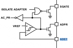
Ah, thank you. As far as I can tell SGATE corresponds to U7000's AGATE and ADET to CHGR_ACIN on U7000. If I understood the block diagram correctly, SGATE is pulled low in case SMC doesn't set the 'ISOLATE ADAPTER' bit and ACIN is greater than the reference voltage.

What I couldn't find is what corresponds to VREF in case of the U7000? Is it VDD-VDDP?

I also noticed that when measuring CHGR_AGATE to ground there is a period where I can measure 0V (good) followed by a period of time where I can measure 16V (bad). After that the smoothing caps (C7030, ...) carry the nominal voltage of ~12V. Is it just my meter bridging to ground or is U7000 switching pin 1 to ground periodically?
 

cmdrdata

macrumors 6502
Jun 10, 2011
377
2
Dallas, Texas, USA
Ah, thank you. As far as I can tell SGATE corresponds to U7000's AGATE and ADET to CHGR_ACIN on U7000. If I understood the block diagram correctly, SGATE is pulled low in case SMC doesn't set the 'ISOLATE ADAPTER' bit and ACIN is greater than the reference voltage.

What I couldn't find is what corresponds to VREF in case of the U7000? Is it VDD-VDDP?

I also noticed that when measuring CHGR_AGATE to ground there is a period where I can measure 0V (good) followed by a period of time where I can measure 16V (bad). After that the smoothing caps (C7030, ...) carry the nominal voltage of ~12V. Is it just my meter bridging to ground or is U7000 switching pin 1 to ground periodically?

CHGR_AGATE is the signal that controls Q7000 (the first FET that allows magsafe power to flow through the charging system). This signal, if all is OK should be "low" or near 0 volt such that the junction voltage at the resistor divider R7098 and R7001 will generate a FET gate turn on voltage of around (62K/(100K+52K)) x 16.5v = 6v.
If the open collector FET inside the U7000-1 is off, then both resistors will float up to 16.5v when measured with a high impedance voltmeter.

Second function is that if battery is good and connected but magsafe is bad or not connected, it shuts of power to the charging circuit (all charging components after Q7000-5 by virtue of pin 1 NOT providing the correct voltage to turn Q7000-4 on.
 

nemo.

macrumors member
May 16, 2013
40
0
CHGR_AGATE is the signal that controls Q7000 (the first FET that allows magsafe power to flow through the charging system). This signal, if all is OK should be "low" or near 0 volt such that the junction voltage at the resistor divider R7098 and R7001 will generate a FET gate turn on voltage of around (62K/(100K+52K)) x 16.5v = 6v.
If the open collector FET inside the U7000-1 is off, then both resistors will float up to 16.5v when measured with a high impedance voltmeter.

Second function is that if battery is good and connected but magsafe is bad or not connected, it shuts of power to the charging circuit (all charging components after Q7000-5 by virtue of pin 1 NOT providing the correct voltage to turn Q7000-4 on.

I'm trying to translate to the schematics of the k90i, please correct me if I'm wrong.

u7000.png

- Your Q7000 is my Q7085.
- R7098 and R7001 are R7085 and R7086 respectively

By pulling U7000-1 low, CHGR_AGATE_DIV will be low enough for Q7085 to activate.

The real question is, however, why this is not the case for me. As I said, judging from the (attached) block diagram of the similar loading chip the following logical expression determines whether U7000-1 is pulled to ground (again, please correct me if I'm wrong):

! (ISOLATE || (VREF > CHGR_ACIN))

This gives me the following options of what goes wrong:

1. SMC set ISOLATE_ADAPTER for some reason
2. SMC communication is broken and ISOLATE_ADAPTER could not be reset (assuming it is set by default)
3. U7000-1 is not soldered correctly
4. U7000 is broken
5. VREF > ACIN

While I can't completely rule out 4. I don't think this is the case as I get
~3.2V for SMC_BC_ACOK and 5V at U7000-VDD. The chip also doesn't get
hot or shows any signs of a defect. I think I can rule out 3 as I tested U7000-1 for continuity with ground, giving me the same result as with measuring from the board.

I'm not sure how I can test 5. as I don't know where U7000 gets its VREF from. Also I don't know how to test for ISOLATE_ADAPTER or the correctness of the SMBus lines. Any idea how to verify these?

EDIT: I should've mentioned that the carger LED (third party charger) is not green, not even dim green.
Could it be that the SMC does not sense the carger and, thus, disables U7000? SYS_ONEWIRE is at 3.4V.
 

Attachments

  • blockdiag.png
    blockdiag.png
    16.5 KB · Views: 241
Last edited:

cmdrdata

macrumors 6502
Jun 10, 2011
377
2
Dallas, Texas, USA
I'm trying to translate to the schematics of the k90i, please correct me if I'm wrong.

View attachment 452240

- Your Q7000 is my Q7085.
- R7098 and R7001 are R7085 and R7086 respectively

By pulling U7000-1 low, CHGR_AGATE_DIV will be low enough for Q7085 to activate.

The real question is, however, why this is not the case for me. As I said, judging from the (attached) block diagram of the similar loading chip the following logical expression determines whether U7000-1 is pulled to ground (again, please correct me if I'm wrong):

! (ISOLATE || (VREF > CHGR_ACIN))

This gives me the following options of what goes wrong:

1. SMC set ISOLATE_ADAPTER for some reason
2. SMC communication is broken and ISOLATE_ADAPTER could not be reset (assuming it is set by default)
3. U7000-1 is not soldered correctly
4. U7000 is broken
5. VREF > ACIN

While I can't completely rule out 4. I don't think this is the case as I get
~3.2V for SMC_BC_ACOK and 5V at U7000-VDD. The chip also doesn't get
hot or shows any signs of a defect. I think I can rule out 3 as I tested U7000-1 for continuity with ground, giving me the same result as with measuring from the board.

I'm not sure how I can test 5. as I don't know where U7000 gets its VREF from. Also I don't know how to test for ISOLATE_ADAPTER or the correctness of the SMBus lines. Any idea how to verify these?

EDIT: I should've mentioned that the carger LED (third party charger) is not green, not even dim green.
Could it be that the SMC does not sense the carger and, thus, disables U7000? SYS_ONEWIRE is at 3.4V.

I think your last statement is the clue. If SMC is not able to communicate with the adapter via pin3 of the magsafe or pin5 of the DCIN board to logic board connector (no green or yellow led), the SMC thinks there is no adapter, thus using the SMBus lines it sets the signal "isolate adapter" to prevent battery power to be wasted in powering the charger circuitry unnecessarily.
VREF is internally generated by the chip, about 3v nominal, I think sourced by battery power.
 

nemo.

macrumors member
May 16, 2013
40
0
I think your last statement is the clue. If SMC is not able to communicate with the adapter via pin3 of the magsafe or pin5 of the DCIN board to logic board connector (no green or yellow led), the SMC thinks there is no adapter, thus using the SMBus lines it sets the signal "isolate adapter" to prevent battery power to be wasted in powering the charger circuitry unnecessarily.
VREF is internally generated by the chip, about 3v nominal, I think sourced by battery power.

Well, as it turns out, U7000-1 was not connected properly. I measured on the chip, this time using a diode tester, and measured a drop of ~100mV. This indicates that U7000 indeed does pull pin 1 to ground. So after dragging a solder ball over the pins I get 16V at C7030.

While this is some progress, I'm still not getting a green light for the charger and only 3.4V at L7030 and F7040. IIRC this should be higher, shouldn't it? I suppose CHGR_UGATE is not working properly but I didn't take measurements so far.
 

cmdrdata

macrumors 6502
Jun 10, 2011
377
2
Dallas, Texas, USA
Well, as it turns out, U7000-1 was not connected properly. I measured on the chip, this time using a diode tester, and measured a drop of ~100mV. This indicates that U7000 indeed does pull pin 1 to ground. So after dragging a solder ball over the pins I get 16V at C7030.

While this is some progress, I'm still not getting a green light for the charger and only 3.4V at L7030 and F7040. IIRC this should be higher, shouldn't it? I suppose CHGR_UGATE is not working properly but I didn't take measurements so far.

Until you get the SMC to know that adapter is present, you won't see 12v at L7030/F7040 (with battery disconnected). You've got to have U7000 to output CHGR_ACOK to logic 1 so that the this signal can turn on U6900-1(google MAX9940) via a signal called SMC_BC_ACK_VCC. Note that SMC_BC_ACOK = CHGR_ACOK = U7000-14
 

chipmunk23

macrumors newbie
Jun 11, 2008
12
1
MacBook Air 2013

I have a MacBook Air 2013 that had some tea...
I cleaned it with alcohol and let it dry.
It works just fine off the battery, BUT when I plug in the MagSafe plug it dims the backlight and a few seconds later even turns off the backlight. The LED on the magsafe plug does not come on.
Does anyone have any clever suggestions as to what is going on?
I can understand the backlight dimming when the power is DISconnected, but this is rather backwards.!?
All help greatly appreciated.
Cheers / Harald
 

Wuchi

macrumors member
Dec 12, 2013
38
0
Finland
I looked again at the dc in board. There is no continuity between the logic board connector pin 5 ( where measured 3,4v) and dc in board middle pin 3. If i understood right, the 3,4v should go to the middle pin of magsafe?

Tomorrow I'll get new dc in board I ordered. Hopefully it solves something.
 

nemo.

macrumors member
May 16, 2013
40
0
Until you get the SMC to know that adapter is present, you won't see 12v at L7030/F7040 (with battery disconnected). You've got to have U7000 to output CHGR_ACOK to logic 1 so that the this signal can turn on U6900-1(google MAX9940) via a signal called SMC_BC_ACK_VCC. Note that SMC_BC_ACOK = CHGR_ACOK = U7000-14

CHGR_ACOK was always "1". Well up until now. I seem to have fried something
after having resoldered one side of U7000. Now almost every important line alternates between 0V and 3V. I seem to have destroyed that U7000. Again.

This might have happened when resoldering the accidentally removed C7050, the 1uF cap between CHGR_CSO_P and CHGR_CSO_N. I seem to have bridged CHGR_CSO_N and CHGR_LGATE... Regarding C7050, can you explain its purpose? I only have 0603 caps around here and no fitting 0402 at hand so I'm considering leaving it removed...
 

cmdrdata

macrumors 6502
Jun 10, 2011
377
2
Dallas, Texas, USA
CHGR_ACOK was always "1". Well up until now. I seem to have fried something
after having resoldered one side of U7000. Now almost every important line alternates between 0V and 3V. I seem to have destroyed that U7000. Again.

This might have happened when resoldering the accidentally removed C7050, the 1uF cap between CHGR_CSO_P and CHGR_CSO_N. I seem to have bridged CHGR_CSO_N and CHGR_LGATE... Regarding C7050, can you explain its purpose? I only have 0603 caps around here and no fitting 0402 at hand so I'm considering leaving it removed...

C7050 is 1uF filter that parallel a current sensing resistors R705x to prevent transient current from impacting the internal comparator inside U7000. Any 1 uF/16v non polarized cap should work, if you can fit it in.
 

dellxps15

macrumors member
Oct 22, 2013
86
0
hi, how did u desolder and resoldered the u7000? i have desoldered the old one but the new one wont solder on the logic board....

CHGR_ACOK was always "1". Well up until now. I seem to have fried something
after having resoldered one side of U7000. Now almost every important line alternates between 0V and 3V. I seem to have destroyed that U7000. Again.

This might have happened when resoldering the accidentally removed C7050, the 1uF cap between CHGR_CSO_P and CHGR_CSO_N. I seem to have bridged CHGR_CSO_N and CHGR_LGATE... Regarding C7050, can you explain its purpose? I only have 0603 caps around here and no fitting 0402 at hand so I'm considering leaving it removed...
 

chigwelldave

macrumors member
Sep 12, 2013
96
0
Adelaide, Australia
Hi Guys,

Anyone know the location of the debug power buttons for the 15" MBP 820-2523-B logic board? Also the codename so I can try to find the schematic and board view?

Regards,

Chigwelldave.
 

nemo.

macrumors member
May 16, 2013
40
0

chipmunk23

macrumors newbie
Jun 11, 2008
12
1
MacBook Air 2013

Still fighting with the MacBook Air from 2013:
Does anyone know if the 'Left I/O & DC-in board' for the 2013 version is compatible with the earlier ones?
mechanically it won't fit obviously, but if at least it was sort of electrically compatible I could use it to distinguish if that board is bad or the motherboard itself.
 

Wuchi

macrumors member
Dec 12, 2013
38
0
Finland
ok, now I've replaced the dc in board and now the green (bright) light is glowing and the mbp starts normally. but the light doesn't turn orange and there where the battery indicator is on the screen reads that it doesn't charge. and there is also notification that I should replace the battery. could bad battery cause the not charging -symptom? this is my first mac and I don't know how it is supposed to react on bad battery.

Thanks!
 

cmdrdata

macrumors 6502
Jun 10, 2011
377
2
Dallas, Texas, USA
ok, now I've replaced the dc in board and now the green (bright) light is glowing and the mbp starts normally. but the light doesn't turn orange and there where the battery indicator is on the screen reads that it doesn't charge. and there is also notification that I should replace the battery. could bad battery cause the not charging -symptom? this is my first mac and I don't know how it is supposed to react on bad battery.

Thanks!

Does it run on battery by itself (assuming it has enough charge to power it)?. If not, then the battery has perhaps reached it's charge cycle count limit and shuts off power output, and in that case the charging circuit will not even turn on to attempt to charge it. There is a difference between "no battery detected" and "replace battery" message. the latter means that the SMS was able to communicate via the SMBus and the battery reporting it has reached the preprogrammed terminal count and shuts off its output. In both cases the SMC will not to turn on the charging system.

if the system will start on that battery only, then you have a charging issue and have to check that portion of the logic.
 

Wuchi

macrumors member
Dec 12, 2013
38
0
Finland
Does it run on battery by itself (assuming it has enough charge to power it)?. If not, then the battery has perhaps reached it's charge cycle count limit and shuts off power output, and in that case the charging circuit will not even turn on to attempt to charge it. There is a difference between "no battery detected" and "replace battery" message. the latter means that the SMS was able to communicate via the SMBus and the battery reporting it has reached the preprogrammed terminal count and shuts off its output. In both cases the SMC will not to turn on the charging system.

if the system will start on that battery only, then you have a charging issue and have to check that portion of the logic.

It didn't run on battery. And it reads 'not charging' besides the battery logo. It needed the magsafe, and it detected the battery, and the I was able to read values (i don't know if these are right words because my snow leopard is in finnish) from 'information about this mac' and choose there 'power'. And there is info like 'power is connected' etc. But there were also voltages and amperes and cycle count. Voltages were 10000 mV and amperes were negative?? And it varied from -1500mA to -870mA depended on when I opened that window again.

And the voltage was reducing. It went down to 9300mA and then it shut down the mac. The green light is on and when I push the power button I can hear either the fan spinning few times or the hard drive, but because it is a ssd drive I don't think it makes any sound?

So the battery is affecting somehow.

Edit. So it doesn't start now. It starts with bypass mode.
 
Last edited:

cmdrdata

macrumors 6502
Jun 10, 2011
377
2
Dallas, Texas, USA
It didn't run on battery. And it reads 'not charging' besides the battery logo. It needed the magsafe, and it detected the battery, and the I was able to read values (i don't know if these are right words because my snow leopard is in finnish) from 'information about this mac' and choose there 'power'. And there is info like 'power is connected' etc. But there were also voltages and amperes and cycle count. Voltages were 10000 mV and amperes were negative?? And it varied from -1500mA to -870mA depended on when I opened that window again.

And the voltage was reducing. It went down to 9300mA and then it shut down the mac. The green light is on and when I push the power button I can hear either the fan spinning few times or the hard drive, but because it is a ssd drive I don't think it makes any sound?

So the battery is affecting somehow.

Edit. So it doesn't start now. It starts with bypass mode.

Get a good/healthy/new replacement battery and try that first. Older MB/MBP with replaceable battery are programmed to shut off after several hundred charge cycle (300?). newer MBP with internal battery can go about 1000 from what I read. Apple does not publish this info so this is only what other people have reported.
 

Wuchi

macrumors member
Dec 12, 2013
38
0
Finland
Get a good/healthy/new replacement battery and try that first. Older MB/MBP with replaceable battery are programmed to shut off after several hundred charge cycle (300?). newer MBP with internal battery can go about 1000 from what I read. Apple does not publish this info so this is only what other people have reported.

Ok. There was over 500 charge cycles with that battery. So I have to get a new battery.

Thank you very much for help! :)

Edit. Actually this is internal battery. The back cover has to be removed before I can get to the battery, and it is attached with two screws.

So the battery should be healthy with 500 charge cycles? How come the amps can have a negative value?
Maybe I'll leave it with magsafe over night and see what has happened in the morning.
 
Last edited:

cmdrdata

macrumors 6502
Jun 10, 2011
377
2
Dallas, Texas, USA
Ok. There was over 500 charge cycles with that battery. So I have to get a new battery.

Thank you very much for help! :)

Edit. Actually this is internal battery. The back cover has to be removed before I can get to the battery, and it is attached with two screws.

So the battery should be healthy with 500 charge cycles? How come the amps can have a negative value?
Maybe I'll leave it with magsafe over night and see what has happened in the morning.

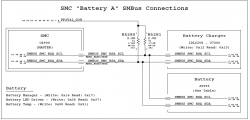
The number of charge cycles for each Mac models is Apple's secret. I'd be interesting to know that myself. However, as shown in the attached picture, it seemed that the SMC communication addresses with a 2008 MacBook or later model MacBookPros have not changed. For example, when the SMC wants to write an update to the battery pack flash memory, it first sends an 8-bit serial address 0x16 (binary 0001 0110) to the BATT followed by another serial data value/code. This is how the battery charge count is incremented. If the SMC wants to know the charge cycle count, it sends a read address of 0x17 (0001 0111) and then waits for the battery to return a serial data transmission indicating count value. If the value is close to "end of life count", the SMC will show "Replace battery" message in the system report. If it doesn't get any serial data response at all, it will probably report "no battery". In models with BIL that are separate from the battery pack, the SMC is the one that turn on the LEDs to indicate battery charge level using address (0x36).
Negative current is the amount of amperage being used/sucked by the system from the power source at that time.
 

Attachments

  • K90i-MBP-SMBUS.png
    K90i-MBP-SMBUS.png
    73.3 KB · Views: 364

Wuchi

macrumors member
Dec 12, 2013
38
0
Finland
Thank you cmdrdata for information.
I ordered a good new battery. See what happens next.

I noticed that I had broken the battery charge indicator that is connected to logic board. The 'wire' was cut allmost in half. I guess I was too rough with it.

Does it affect some error to smc or can I just leave it as it is?

Thanks!
 
Register on MacRumors! This sidebar will go away, and you'll see fewer ads.