Become a MacRumors Supporter for $50/year with no ads, ability to filter front page stories, and private forums.
Status
The first post of this thread is a WikiPost and can be edited by anyone with the appropiate permissions. Your edits will be public.

terraphantm

macrumors 68040
Jun 27, 2009
3,816
670
Pennsylvania
Wow, You mean you can hibernate your MBP2014 mid from now on?
How did you do that? Do you have a SPI programmer?
Yes I have a programmer (in this case I used a GQ-4X which I had from my car hacking days, but there's a bunch that should work). I also have a rasberry pi which should work. Everything works, except in the EFI boot menu the drive icon shows as external (I wonder if there's a whitelist of drives somewhere?).

what's your model ?
My MBP mid 2014

Same here on mine with the EX920. Same controller (Silicon Motion SM2262) and flash (Intel-Micron Flash Technologies) as the Intel 760p. I think the Adata XPG SX8200 also uses the same controller and flash. I do wish I took note of what the power consumption was with the stock SSD. But right now it seems like simply using Chrome is a much bigger battery sink than anything else.

Screen Shot 2018-06-08 at 9.57.14 PM.png


It presently is the only known way to flash the bootrom with a hacked/modified one in these machines.

Since I have a reliable flashing setup and an extra macbook, I'm going to experiment with finding a way to force the laptop into flashing mode. Maybe corrupting a portion of it would do the trick
 
  • Like
Reactions: l_zhang

vk2fro

macrumors member
Apr 29, 2015
99
51
Sydney, Australia
Since I have a reliable flashing setup and an extra macbook, I'm going to experiment with finding a way to force the laptop into flashing mode. Maybe corrupting a portion of it would do the trick

Hehe I like your thinking... you can always use your SPI programmer to revert back to the working bootrom if corrupting it bricks the machine. Even an extra macbook isn't necessary to repair it, you could use a raspberry pi to do all the work if you set it up with a bluetooth keyboard and mouse, and plug its HDMI into a television. Of course you'd only be using that to reflash the backup rom back to the board to get it booting again, so you can use UEFItool, etc.

Regarding orange or silver (ext vs int) drive icons, its a crap shoot as to wether you get either, like playing a slot machine - although the odds are definatly stacked against you in the latter - it doesn't affect functionality. Fair point though, there could be a whitelist in the bios somewhere - like what IBM/Lenovo does for wifi cards.


Honestly, unless forum members like taking risks, everyone who plans on doing firmware level hacks that presents a risk of bricking expensive hardware should have a backup plan. I know I've ordered raspberry pi's but they're cheap and easy to come by, I do have a couple of SPI flashers here also, a CH341 and one similar to gilles_polysoft, just can't put my hands on the second one - When I tidy the area next to the book case, I'll probably find it and a few other bits and bobs, just need to get motivated to move a bigass argon laser thats in the way :p
 

imax2k2

macrumors regular
Feb 25, 2009
107
9
Hehe I like your thinking... you can always use your SPI programmer to revert back to the working bootrom if corrupting it bricks the machine. Even an extra macbook isn't necessary to repair it, you could use a raspberry pi to do all the work if you set it up with a bluetooth keyboard and mouse, and plug its HDMI into a television. Of course you'd only be using that to reflash the backup rom back to the board to get it booting again, so you can use UEFItool, etc.

Regarding orange or silver (ext vs int) drive icons, its a crap shoot as to wether you get either, like playing a slot machine - although the odds are definatly stacked against you in the latter - it doesn't affect functionality. Fair point though, there could be a whitelist in the bios somewhere - like what IBM/Lenovo does for wifi cards.

Honestly, unless you like taking risks, everyone who plans on doing firmware level hacks that presents a risk of bricking expensive hardware should have a backup plan. I know I've ordered raspberry pi's but they're cheap and easy to come by, I do have a couple of SPI flashers here also, a CH341 and one similar to gilles_polysoft, just can't put my hands on the second one - When I tidy the area next to the book case, I'll probably find it and a few other bits and bobs, just need to get motivated to move a bigass argon laser thats in the way :p

Could something like this work?

https://rover.ebay.com/rover/0/0/0?mpre=https://www.ebay.com/ulk/itm/172710937959

This ones pretty cheap, but would it work over USB? Since I have never done this, some help on how to do it would be helpful.
 

vk2fro

macrumors member
Apr 29, 2015
99
51
Sydney, Australia
it may - however you might need to bolster the 3.3 ish V across pins 8 and 4 of the chip like Gilles_Polysoft had to do with his programmer. Before trying anything with those plug in style units, check the voltage on pins 8 and 4. It should read around 3.3 - 3.4.

The reason for this is you need to boost the current when the chip is in situ, as your powering other board level components, and this causes the voltage to sag on a weak power supply. Thats how you get read errors.

Over on another forum (ghostlyhaks) they have had plenty of success with raspberry pi's - they supply enough current to power the board level stuff as well as the spi chip we're trying to program. Almost free too - about $10 for a pi zero. They're pretty simple to set up, and if you only have one computer, provided you store the backup on the pi, you can plug it into a TV, hook up to a keyboard and mouse, and restore the backup rom if you mess up the rom editing. I plan to give full instructions once my clip arrives.
 
Last edited:

imax2k2

macrumors regular
Feb 25, 2009
107
9
it may - however you might need to bolster the 3.3 ish V across pins 8 and 4 of the chip like Gilles_Polysoft had to do with his programmer. Before trying anything with those plug in style units, check the voltage on pins 8 and 4. It should read around 3.3 - 3.4.

The reason for this is you need to boost the current when the chip is in situ, as your powering other board level components, and this causes the voltage to sag on a weak power supply. Thats how you get read errors.

Personally and as I have one, I'll be using my variable bench supply to power the 3.3V supply, thus mitigating this problem.

How is that done? increasing the voltage, I do have a voltmeter to check the voltage.

Thanks
 

vk2fro

macrumors member
Apr 29, 2015
99
51
Sydney, Australia
No you do not increase the voltage!! that will fry components. You need a current source. That little programmer would probably not be able to source enough current at 3.3v as the usb port powering it is limited to 1/2 an amp, which becomes even less thanks to losses in the dc-dc converter.
 

terraphantm

macrumors 68040
Jun 27, 2009
3,816
670
Pennsylvania
So I did find this: https://www.win-raid.com/t3553f39-G...ite-Access-Permissions-for-SPI-Servicing.html

Apparently pulling HDA_SDO (which should be somewhere on the audio chip) high disables the lock for a single boot. The audio chip on the macbook pro appears to be a BGA IC so that won't work, but perhaps there's a header or test pad somewhere with that line exposed. Wish I could non-destructively determine that. May also be possible to trigger something with the EFI shell, but I suspect Apple locked that down sufficiently.
 

terraphantm

macrumors 68040
Jun 27, 2009
3,816
670
Pennsylvania
Very interesting read - hah! whoda thought shorting two pins on the audio chip would unlock a chip thats probably in the next suburb (on the other side of the board)! :)
[doublepost=1528515443][/doublepost]I found this which might be useful - schematics!! :)

https://drive.google.com/drive/u/0/folders/0B8B-49GBfTbNckFKRm1UVTlNaDg
Woah, that's awesome. So 827-3787A seems to be the Late-2013 15" MBP (or maybe it's a 2015 - these are probably mastered well before release) which should be more or less the same as the Mid-2014. Page 19 of the PDF in there seems to describe a device labeled "Q1920" that is wired to the HDA_SDOOUT for the purpose of SPI flashing

If I'm reading the document correctly, the SMC can trigger "SPI_DESCRIPTOR_OVERRIDE_L", which would trigger a downstream circuit to pull "SPI_DESCRIPTOR_OVERRIDE" and ultimately "HDA_SDOUT_R" high. I don't know if *we* can trigger the SMC to send that command, but if we can identify the circuit, it could just be a matter of shorting it while the system boots.
 
Last edited:

vk2fro

macrumors member
Apr 29, 2015
99
51
Sydney, Australia
And the 3.3v line should be available on dozens of points around the board! Now I wish I could find the 820 number for the late 2013 mbp retina!

edit: found it - 820-3476-a : 2.8Ghz 16Gb MBPr late 2013 :)
 

terraphantm

macrumors 68040
Jun 27, 2009
3,816
670
Pennsylvania
And the 3.3v line should be available on dozens of points around the board! Now I wish I could find the 820 number for the late 2013 mbp retina!
For the 13 inch? Yeah that doesn't seem to be there. I do see the late 2012 though. I imagine the components involved are very likely to be the same for most of the MBPs.

I wonder how we'd go about identifying the correct IC -- doesn't seem like the logicboards are actually labeled.
 

vk2fro

macrumors member
Apr 29, 2015
99
51
Sydney, Australia
Yeah its there - I edited my post - the cirrus logic chip near the right (with the battery facing you) is the audio ic in these machines. One of the transistors should be Q1920 - its the same transistor as in your model :)

Has anyone noticed that the audio is muted (chimes) while installing the OS? You only hear the chime when the final stage of os installation is started (booting to the setup screen). Wonder if they are related?
 

terraphantm

macrumors 68040
Jun 27, 2009
3,816
670
Pennsylvania
Looks like it should be a DMN5L06VK-7 specifically. Should look something like this
dmn5l06vk-7_sml.jpg


I see a promising 6-pin near the Cirrus chip on the ifixit teardowns. Hopefully that's the one rather than something on the other side of the board (at which point it would be easier to just use an SPI programmer)
 

vk2fro

macrumors member
Apr 29, 2015
99
51
Sydney, Australia
Yep thats the little bugger - I'm trying to hunt down boardview files to verify... :)
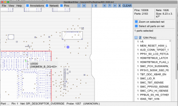
[doublepost=1528521186][/doublepost]FOUND it! other side of the board, but the testpoint comes out on the top side of the logic board! so one should be able to take that high to 3.3V (with a 33K resistor) and bypass the lock.

I've attached a screen shot - the testpoint is the one left of the purple dot.
 

Attachments

  • Screen Shot 2018-06-09 at 3.14.33 pm.png
    Screen Shot 2018-06-09 at 3.14.33 pm.png
    234.9 KB · Views: 275
Last edited:

vk2fro

macrumors member
Apr 29, 2015
99
51
Sydney, Australia
Yeah I know the gunk you mean - I had the base off the 13 inch before to find the board model number, but have since reassembled it - once a day is enough LOL!

The only way to get to it would be to soften the gunk (mabye nail polish remover or isopropyl alcohol would work) and CAREFULLY scrape it away. Another way (if you have a steady hand like me, unless you have had too much coffee) is to melt the gunk with a soldering iron then polish up with the tip of a spudger. A third is VERY gently application of a dremel tool, and suitable bit, on a low speed. I would not attack that gunk with anything sharp - you don't want to scratch your MLB and risk killing it.

Heres my thoughts for easy flashing - install a 2 pin header wired to that testpoint along with a resistor, and install the jumper whenever one needs to flash. Glue the header right next to the PCH on top of the gunk, make that gunk serve two purposes ;)
 
Last edited:

terraphantm

macrumors 68040
Jun 27, 2009
3,816
670
Pennsylvania
Well actually now that I look closer, the SPI_PIN_OVERRIDE test point appears to be just barely accessible, though the solder mask would have to be scratched away to use it.

Otherwise SPI_DESCRIPTOR_OVERRIDE_L may be accessible under the wifi card.

All that said, it might be worth exploring the SMC, since the purpose of the circuit seems to be to allow the SMC to pull the strap.
 

terraphantm

macrumors 68040
Jun 27, 2009
3,816
670
Pennsylvania
Yeah I'm getting confused the more I look at the diagram. As for as SPI_PIN_OVERRIDE goes, it seems to be connected to the HDA_SDO via a 1K resistor. So I think pulling that high would do the trick
 

vk2fro

macrumors member
Apr 29, 2015
99
51
Sydney, Australia
Are you referring to SPI_DESCRIPTOR_OVERRIDE? if so thats the purple dot in my screengrab. And yes it does indeed connect to HDA_SDOUT_R via a 1K.
 

terraphantm

macrumors 68040
Jun 27, 2009
3,816
670
Pennsylvania
Ah. I was originally looking at the test point that goes directly to HDA_SDOUT_R. That one is either not present on the final board or under the gunk.

SPI_DESCRIPTOR_OVERRIDE appears to be accessible (though it's under solder mask). The gunk is so close, I imagine some people's macbook pros might have it completely covered
Screen Shot 2018-06-09 at 2.25.22 AM.png
IMG_1810.jpg


Then SPI_DESCRIPTOR_OVERRIDE_L is under the wifi card based on the brd file, though I'm not sure the point is actually present on the non engineering boards.
Screen Shot 2018-06-09 at 2.26.42 AM.png
IMG_1812.jpg
 

vk2fro

macrumors member
Apr 29, 2015
99
51
Sydney, Australia
See the 3 pads in the middle, leftmost (near the cable) of your pic that are in a row on an angle similar to between 11 and 12 oclock on a watch face? The middle guy is SPI_DESCRIPTOR_OVERRIDE_L :)
 

vk2fro

macrumors member
Apr 29, 2015
99
51
Sydney, Australia
Pull that baby high (3,3V via suitable resistor e.g. 100k - work down) and as us aussies says (and dave jones from EEVBLOG on youtube would) "your in like flynn" :)

It only needs to be temporary - once the apple appears and loading starts, you can remove the assertion.

If this works, no raspberry pi's, no spi flashers, just a soldering iron and a resistor :p

heres its location on the 13" model - no need to even pull the wifi card!

To verify its enabled, run ahd, and you'll get a PFM006 error, or simply dump and then try reflashing the current bios with dosdudes tool. Fans will probably ramp up to full too :p
 

Attachments

  • Screen Shot 2018-06-09 at 4.51.08 pm.png
    Screen Shot 2018-06-09 at 4.51.08 pm.png
    38.4 KB · Views: 221
Last edited:

terraphantm

macrumors 68040
Jun 27, 2009
3,816
670
Pennsylvania
If I'm reading the diagram right, it might actually need to be pulled low (might default high?). It looks like if it's pulled high, SPI_DESCRIPTOR_OVERRIDE_LS5V will be pulled low, which would disconnect PI_DESCRIPTOR_OVERRIDE from PP1V5_S0. If that's the case, then one just has to ground the point, which is even easier.
 
Register on MacRumors! This sidebar will go away, and you'll see fewer ads.