Become a MacRumors Supporter for $50/year with no ads, ability to filter front page stories, and private forums.

mac-n-sauce

macrumors regular
Jun 25, 2012
209
2
Tampa, Fl
Might be the charger then. I characterized a known good charger all pins resistance to ground. Can't remember if I ever posted it but it is a good diagnostics tool to indicate issues. In particular check the 2 charger outputs that go to the gates of the drive FETS. I think they are something like pin 22, 23. No schematic handy so just from memory.

Good memory
Pins 21 and 24
I have a fluctuating 16.5 to 17.05 volts pin 5(Q7020) Pin 4 .10v to pin 24 Charger UGate
Q7021 have .10v pin 5 and nothing pin 4 to Charger LGate

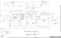
I attached schematic page Dadioh maybe it will help.

Does this mean that Q7021 is bad?
 

Attachments

  • Screen Shot 2012-08-25 at 7.02.35 PM.png
    Screen Shot 2012-08-25 at 7.02.35 PM.png
    255.8 KB · Views: 578

jlsinger

macrumors newbie
Aug 15, 2012
9
0
MBP A1278 Mid 2010 - Help!

Hi All and Thank you in advance!

In trying to get my backlight working, I made a HUGE mistake soldering a cap near the LP8545 WLED driver with battery connected. :eek: After realizing what I had done, I tried to start. I can hear the drive start, but nothing else. This happens on both battery and power adapter. I can do SMC bypass, which starts machine and magsafe goes green to amber with fans at full speed. Previous to my mistake, everything except backlight worked. I still dont have backlight, but first I obviously need to get back to where I was before my stupid error!

Reading through this thread, most issues relate to battery or power adapter not functioning that doesnt relate to my issue.

Can anyone can stear me in the right direction?
 

U-234

Suspended
May 16, 2012
72
0
Chicago, IL
Might be the charger then. I characterized a known good charger all pins resistance to ground. Can't remember if I ever posted it but it is a good diagnostics tool to indicate issues. In particular check the 2 charger outputs that go to the gates of the drive FETS. I think they are something like pin 22, 23. No schematic handy so just from memory.

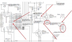
But sometimes that might be problematic. Let's say my IC Charger pin 24 UGate has wrong impedience to ground, does this mean it is only isolated to our charger chip or maybe because Ugate feeds to the Q7030 FET (pin4 gate) now it might be the issue with the Mosfet not the Charger Chip? (Please look at the attached picture so see the component dependance on each other)

Do you see my point Dadioh? Because there is more than one component in our ciruit is it hard to pin point which chip is it(they effect each other's readings). We can always 'brute force it' and just replace both Mosfet and Charger but sometimes it might be not necessary if only one is the culprint.

I have been playing with A1278 LB type for months, I pretty much memorized all the components and in many cases narrowed down the issue to 3-4 components, now like described above finding which one exactly is the culprit since they share the same connection/line is the main problem.

If the component 2 will effect the readings of the component 1 and component 3 deciding which one is the source of the issue is to me the most difficult.
 

Attachments

  • Capture.PNG
    Capture.PNG
    118.1 KB · Views: 508

mac-n-sauce

macrumors regular
Jun 25, 2012
209
2
Tampa, Fl
But sometimes that might be problematic. Let's say my IC Charger pin 24 UGate has wrong impedience to ground, does this mean it is only isolated to our charger chip or maybe because Ugate feeds to the Q7030 FET (pin4 gate) now it might be the issue with the Mosfet not the Charger Chip? (Please look at the attached picture so see the component dependance on each other)

Do you see my point Dadioh? Because there is more than one component in our ciruit is it hard to pin point which chip is it(they effect each other's readings). We can always 'brute force it' and just replace both Mosfet and Charger but sometimes it might be not necessary if only one is the culprint.

I have been playing with A1278 LB type for months, I pretty much memorized all the components and in many cases narrowed down the issue to 3-4 components, now like described above finding which one exactly is the culprit since they share the same connection/line is the main problem.

If the component 2 will effect the readings of the component 1 and component 3 deciding which one is the source of the issue is to me the most difficult.

Doesn't The Q7030 feed pin 5 of Q7035 on this 2010 MBP? I am working o the 2009 and they are called Q7020 and Q7021 and it does not have the resistor (R7039) so I just have two devices, but since I have only two, wouldn't that make my Q7020 bad since it is first? I am just assuming, because I am learning how to read the schematics.(rookie :)
 

kilgrinus

macrumors newbie
Aug 12, 2012
14
0
I am on the 2009 model MBP and it has the 47ohm instead of the 1 ohm like the 2010
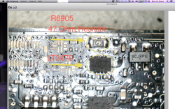
I attached schematic page. Would a bad LT3470 make that 47 ohm resistor get that hot? Is there a resistor i could solder over it to drop the voltage. I tried soldering a 47 ohm resistor on top of the original thinking the resistor was bad but it still had around 6v on G3HOT.

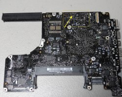
Can you post a pic of where the resistor and LT3470 are located on the board.
 

Ratjetoe

macrumors newbie
Aug 26, 2012
8
0
Macbook Pro 13" 2010 2,4Ghz problem

Today I opened my Macbook to install a SSD. After I did that, and started my MacBook, fans where 100%. Strange...

MacBook was slow and when I tried to restart without the AC in, it wont start.

So I opened it, took my SSD out, Optical drive back. But still the same problems.

Green light of Magsafe is burning and only starts with Magsafe connected. Doesn't recognize the battery (x symbol) and the fans are 100% when you start it.

So i searched a lot already, tried SMC reset, PRAM reset..but nothing worked.....


I don't know what I did wrong. I thought putting a SSD in my MacBook was simple. Already did it in my 27" iMac a year ago and its working perfectly there...

What can I do? Can you guys help me out?
 

mac-n-sauce

macrumors regular
Jun 25, 2012
209
2
Tampa, Fl
Can you post a pic of where the resistor and LT3470 are located on the board.

Bottom of board 1.5" west of lvds connector. It is very small right at the northern edge of board.
 

Attachments

  • MBP 13' 2.26.jpg
    MBP 13' 2.26.jpg
    1.6 MB · Views: 506
  • Screen Shot 2012-08-26 at 6.29.51 PM.png
    Screen Shot 2012-08-26 at 6.29.51 PM.png
    2.2 MB · Views: 704

U-234

Suspended
May 16, 2012
72
0
Chicago, IL
Doesn't The Q7030 feed pin 5 of Q7035 on this 2010 MBP? I am working o the 2009 and they are called Q7020 and Q7021 and it does not have the resistor (R7039) so I just have two devices, but since I have only two, wouldn't that make my Q7020 bad since it is first? I am just assuming, because I am learning how to read the schematics.(rookie :)

The one that i'm working on is Early 2011 so yours might be slightly different but in general they are very similar, like you said on yours FETS are Q7021 and Q7020 on mine Q7035 and Q7030. Now the source of Q7030 connects to the drain of Q7035 and PIN 23 [CHGR_PHASE] of the IC Charger so now let's assume my resistance on the source is abnormal, that might be caused by 3 componets.

On my other LB also Early 2011 I lost power on the main F7040 near the battery, this is the main fuse before it goes to the system. If you have 0V on it our LB is dead and won't power on. Also, F7040 feeds directly to IC Charger via CHGR_PHASE so if the IC Charger is bad it can cause 0V on the fuse.

I replaced the charger twice, since it has 28 pins (QFN) it is very difficult to solder, even if you think it looks good, you not sure if it all the pads are making good connection.

It appears your voltage is off little bit.

On mine Q7030
Pin4=12V

Q7035
Pin4=0V
Pin5-8=12V

I'm sorry what was your original issue here, battery not charging?
 
Last edited:

Dadioh

macrumors 65816
Original poster
Feb 3, 2010
1,123
36
Canada Eh?
But sometimes that might be problematic. Let's say my IC Charger pin 24 UGate has wrong impedience to ground, does this mean it is only isolated to our charger chip or maybe because Ugate feeds to the Q7030 FET (pin4 gate) now it might be the issue with the Mosfet not the Charger Chip? (Please look at the attached picture so see the component dependance on each other)

Do you see my point Dadioh? Because there is more than one component in our ciruit is it hard to pin point which chip is it(they effect each other's readings). We can always 'brute force it' and just replace both Mosfet and Charger but sometimes it might be not necessary if only one is the culprint.

I have been playing with A1278 LB type for months, I pretty much memorized all the components and in many cases narrowed down the issue to 3-4 components, now like described above finding which one exactly is the culprit since they share the same connection/line is the main problem.

If the component 2 will effect the readings of the component 1 and component 3 deciding which one is the source of the issue is to me the most difficult.

Agreed. But after assuming in several cases (wrongly) that the FET's were bad and replacing them I have since discovered that the majority of times it is the charger IC. Since the FET's are easy to remove and replace the best approach is to remove the one showing low impedance and see if the problem still exists. If so, then the charger IC is bad. That's why I keep 5 to 10 charger IC's in stock. I have replaced about 5 of them in the last few months.
 

mac-n-sauce

macrumors regular
Jun 25, 2012
209
2
Tampa, Fl
The one that i'm working on is Early 2011 so yours might be slightly different but in general they are very similar, like you said on yours FETS are Q7021 and Q7020 on mine Q7035 and Q7030. Now the source of Q7030 connects to the drain of Q7035 and PIN 23 [CHGR_PHASE] of the IC Charger so now let's assume my resistance on the source is abnormal, that might be caused by 3 componets.

On my other LB also Early 2011 I lost power on the main F7040 near the battery, this is the main fuse before it goes to the system. If you have 0V on it our LB is dead and won't power on. Also, F7040 feeds directly to IC Charger via CHGR_PHASE so if the IC Charger is bad it can cause 0V on the fuse.

I replaced the charger twice, since it has 28 pins (QFN) it is very difficult to solder, even if you think it looks good, you not sure if it all the pads are making good connection.

It appears your voltage is off little bit.

On mine Q7030
Pin4=12V

Q7035
Pin4=0V
Pin5-8=12V

I'm sorry what was your original issue here, battery not charging?

Q7020=Q7030 pin 4 = .10v, Pin 5 fluctuating 15-17v
Q7021=Q7035 pin 4 = 0v, Pin 5 =.10v

2009 MBP 13":My magsafe charger flashes green , G3HOT 3.39v, does not boot.
 
Last edited:

Dadioh

macrumors 65816
Original poster
Feb 3, 2010
1,123
36
Canada Eh?
Q7020=Q7030 pin 4 = .10v, Pin 5 fluctuating 15-17v
Q7021=Q7035 pin 4 = 0v, Pin 5 =.10v

2009 MBP 13":My magsafe charger flashes green , G3HOT 3.39v, does not boot.

Q7021 pin 5 is the boosted charge voltage so it should be something like 12.5V.

With power removed can you measure resistance

Q7020 pin 4 to pin 1,2,3. Should be a high impedance.
Q7021 pin 4 to pin 1,2,3. Should be about 20kohms.

Be careful. If you measure too soon after board has been powered down there is enough capacitance that a charge remains that fools the ohmmeter into thinking it is a short circuit. If you are in a hurry you can take a wire connected to board ground and touch to all the FET pins to make sure it is discharged before measuring.
 

mac-n-sauce

macrumors regular
Jun 25, 2012
209
2
Tampa, Fl
Q7021 pin 5 is the boosted charge voltage so it should be something like 12.5V.

With power removed can you measure resistance

Q7020 pin 4 to pin 1,2,3. Should be a high impedance.
Q7021 pin 4 to pin 1,2,3. Should be about 20kohms.

Be careful. If you measure too soon after board has been powered down there is enough capacitance that a charge remains that fools the ohmmeter into thinking it is a short circuit. If you are in a hurry you can take a wire connected to board ground and touch to all the FET pins to make sure it is discharged before measuring.

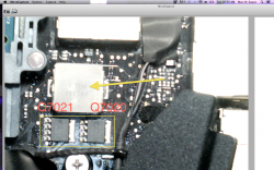
If I am looking at the board and the fet's are at the top:
Is Q7020 the right one and Q7021 the left?

Here is what I have. The board has been powered off all day.

The right hand one has 20k
The left has 5K
My meter is set at 200k scale
 

Dadioh

macrumors 65816
Original poster
Feb 3, 2010
1,123
36
Canada Eh?
If I am looking at the board and the fet's are at the top:
Is Q7020 the right one and Q7021 the left?

Here is what I have. The board has been powered off all day.

The right hand one has 20k
The left has 5K
My meter is set at 200k scale

Not sure which is which off the top of my head but the 20k reading sounds correct for q7021. Q7020 should be higher than 5k I believe. Measure them on a known good board to be sure. To check if it is the fet or the charger ic remove the fet with hot air tool and see if high resistance restored.
 

mac-n-sauce

macrumors regular
Jun 25, 2012
209
2
Tampa, Fl
Not sure which is which off the top of my head but the 20k reading sounds correct for q7021. Q7020 should be higher than 5k I believe. Measure them on a known good board to be sure. To check if it is the fet or the charger ic remove the fet with hot air tool and see if high resistance restored.

I discovered that the left one is the Q7021. On the 2010 model they have different package numbers so I compared locations to the 2009.

I also checked 3 other boards I am working on. They all measured the same. Those boards are not working either so who knows. I will test on a known good board tomorrow.

I practiced trying to remove a fet off an old 2006 board today with my hot air station set at 400. Could not get it off. Is there a trick? Should I be using liquid flux. Sorry i am such a novice at this.

Ok, checked known good board:
Q7021 reads 5.1k on pins 1-3
Q7020 reads 0.0 on pins 1-3

Then I plugged the magsafe in
Q7020 pin 5 = 16.58v
pins 1-3 = 12.58v
pin 4 = 13.48v
Q7021 pin 5 = fluctuates +/- 0 to .01
pins 1-3 =0 I guess thats ground
pin 4 = .54v
 
Last edited:

U-234

Suspended
May 16, 2012
72
0
Chicago, IL
Q7020=Q7030 pin 4 = .10v, Pin 5 fluctuating 15-17v
Q7021=Q7035 pin 4 = 0v, Pin 5 =.10v

2009 MBP 13":My magsafe charger flashes green , G3HOT 3.39v, does not boot.

So definately your values on both FETS are no good. Since we not sure if the charger is the culprit here, like Dadioh said we can try to start replacing the fets (since it is much easier then the IC Charger)

The only scenerio is if the charger is bad and you will replace both fets they might blow again. What you think Dadioh worth the try?

How many in your cases charging issue was caused by the FETS and how many times by the IC Charger itself?
 

kilgrinus

macrumors newbie
Aug 12, 2012
14
0
So definately your values on both FETS are no good. Since we not sure if the charger is the culprit here, like Dadioh said we can try to start replacing the fets (since it is much easier then the IC Charger)

The only scenerio is if the charger is bad and you will replace both fets they might blow again. What you think Dadioh worth the try?

How many in your cases charging issue was caused by the FETS and how many times by the IC Charger itself?

Could one of these FETS be bad if it still boots on battery alone but not magsafe alone or does that indicate a bad charger IC?
 

Dadioh

macrumors 65816
Original poster
Feb 3, 2010
1,123
36
Canada Eh?
Could one of these FETS be bad if it still boots on battery alone but not magsafe alone or does that indicate a bad charger IC?

I guess if the lower FET Q7021 was shorted to ground then the battery would not be able to sustain a voltage on the system bus. So you might be right for that instance.

----------

I discovered that the left one is the Q7021. On the 2010 model they have different package numbers so I compared locations to the 2009.

I also checked 3 other boards I am working on. They all measured the same. Those boards are not working either so who knows. I will test on a known good board tomorrow.

I practiced trying to remove a fet off an old 2006 board today with my hot air station set at 400. Could not get it off. Is there a trick? Should I be using liquid flux. Sorry i am such a novice at this.

Ok, checked known good board:
Q7021 reads 5.1k on pins 1-3
Q7020 reads 0.0 on pins 1-3

Then I plugged the magsafe in
Q7020 pin 5 = 16.58v
pins 1-3 = 12.58v
pin 4 = 13.48v
Q7021 pin 5 = fluctuates +/- 0 to .01
pins 1-3 =0 I guess thats ground
pin 4 = .54v

Q7020 pins 1-3 are right at 12.6V but they are the same point as Q7021 pin 5 so I can't see how you are only measuring 0V? Are you measuring the right FET's. Q7020/21 are located on the back of the board opposite the charger.

To remove I set my hot air tool to 500F and use a small nozzle about the same size as the FET package itself and place it almost on top of the package. Takes about 30-40 seconds of heat before I see the solder melting. I then use tweezers to lift it directly off the board. Do not slide it or you can wipe other components off the board.
 

mac-n-sauce

macrumors regular
Jun 25, 2012
209
2
Tampa, Fl
I guess if the lower FET Q7021 was shorted to ground then the battery would not be able to sustain a voltage on the system bus. So you might be right for that instance.

----------


Q7020 pins 1-3 are right at 12.6V but they are the same point as Q7021 pin 5 so I can't see how you are only measuring 0V? Are you measuring the right FET's. Q7020/21 are located on the back of the board opposite the charger.

To remove I set my hot air tool to 500F and use a small nozzle about the same size as the FET package itself and place it almost on top of the package. Takes about 30-40 seconds of heat before I see the solder melting. I then use tweezers to lift it directly off the board. Do not slide it or you can wipe other components off the board.

I am sorry, you are right. it was late last night. Pin 5 Q7021 is also 12.6v
Yes these are the FET's on the back of the board opposite the charger right below the L7000 Inductor.

So, based on the values i am getting:
Q7020=Q7030 pin 4 = .10v, Pin 5 fluctuating 15-17v
Q7021=Q7035 pin 4 = 0v, Pin 5 =.10v

2009 MBP 13":My magsafe charger flashes green , G3HOT 3.39v, does not boot.

It appears that Q7021 is working taking .10v from pin 4gate on Q7020 but is only getting .10v instead of 12.6v from pin 4 on Q7020.

So would it stand to reason that either Q7020 is bad, or what is feeding Q7020?
Since the voltage is fluctuating on pin 5 Q7020.

So feeds Pin 5 Q7020?
By the way, do we have to replace with the exact Power MosFet? I am working on the 2009 and 2010 and they are different numbers. Same manufacturer

This kind of feels like Sherlock Holmes work! :)
 

Attachments

  • Screen Shot 2012-08-28 at 10.30.42 AM.png
    Screen Shot 2012-08-28 at 10.30.42 AM.png
    1.6 MB · Views: 389

cmdrdata

macrumors 6502
Jun 10, 2011
377
2
Dallas, Texas, USA
I am sorry, you are right. it was late last night. Pin 5 Q7021 is also 12.6v
Yes these are the FET's on the back of the board opposite the charger right below the L7000 Inductor.

So, based on the values i am getting:
Q7020=Q7030 pin 4 = .10v, Pin 5 fluctuating 15-17v
Q7021=Q7035 pin 4 = 0v, Pin 5 =.10v

2009 MBP 13":My magsafe charger flashes green , G3HOT 3.39v, does not boot.

It appears that Q7021 is working taking .10v from pin 4gate on Q7020 but is only getting .10v instead of 12.6v from pin 4 on Q7020.

So would it stand to reason that either Q7020 is bad, or what is feeding Q7020?
Since the voltage is fluctuating on pin 5 Q7020.

So feeds Pin 5 Q7020?
By the way, do we have to replace with the exact Power MosFet? I am working on the 2009 and 2010 and they are different numbers. Same manufacturer

This kind of feels like Sherlock Holmes work! :)

Jumping into the frey: if the UGATE or LGATE signals are both low (pin 4 of the power FETs aka pin 24 and 21 of the charger IC, I suspect that the ISL6258 is bad. When running normally, UGATE and LGATE will alternately pulses to Vgs threshold levels so that they are turning Q7020 and Q7021 to be around a 70% and 30% duty cycle to create a chopped 16.5 v output that is then smoothed by L7000 and that becomes 12v power to the system. If the system works on battery alone, that means that power is getting to the system through R7008 (a 0.1 Ohm resistor). The FETs are not on and thus not charging the battery.

EDIT: fluctuating 15-17v is not a concern at this time. If replacing FET they must be of the same rating and p-channel or n-channel type.
 
Last edited:

mac-n-sauce

macrumors regular
Jun 25, 2012
209
2
Tampa, Fl
Jumping into the frey: if the UGATE or LGATE signals are both low (pin 4 of the power FETs aka pin 24 and 21 of the charger IC, I suspect that the LT3470 is bad. When running normally, UGATE and LGATE will alternately pulses to Vgs threshold levels so that they are turning Q7020 and Q7021 to be around a 70% and 30% duty cycle to create a chopped 16.5 v output that is then smoothed by L7000 and that becomes 12v power to the system. If the system works on battery alone, that means that power is getting to the system through R7008 (a 0.1 Ohm resistor). The FETs are not on and thus not charging the battery.

EDIT: fluctuating 15-17v is not a concern at this time. If replacing FET they must be of the same rating and p-channel or n-channel type.

So you are saying that the LT3470 sends the power to the fet's
 

cmdrdata

macrumors 6502
Jun 10, 2011
377
2
Dallas, Texas, USA
So you are saying that the LT3470 sends the power to the fet's

Yup. The FETs there are like switches that gets turn on/off commands (via Upper and Lower GATE signals) from the ISL6258. The duration of off/on is modulated by the ISL6258 so that it generates the proper voltage that controls the charging current into the battery. The voltage across R7008 is that sensor that the ISL6258 measures and thus knows how much charging current is flowing to/from the battery. When the battery s fully charged, Q7050 will be commanded to shut off so that the system only uses magsafe power.

EDIT: Oops, major boo boo. I am thinking of the ISL6258 NOT LT 3470 in my last 2 posts. Sorry. LT3470 is strictly a 3.42v voltage regulator
 
Last edited:

mac-n-sauce

macrumors regular
Jun 25, 2012
209
2
Tampa, Fl
Yup. The FETs there are like switches that gets turn on/off commands (via Upper and Lower GATE signals) from the ISL6258. The duration of off/on is modulated by the ISL6258 so that it generates the proper voltage that controls the charging current into the battery. The voltage across R7008 is that sensor that the ISL6258 measures and thus knows how much charging current is flowing to/from the battery. When the battery s fully charged, Q7050 will be commanded to shut off so that the system only uses magsafe power.

EDIT: Oops, major boo boo. I am thinking of the ISL6258 NOT LT 3470 in my last 2 posts. Sorry. LT3470 is strictly a 3.42v voltage regulator

Swapped it out, getting pulsing 16.5v pins 6,8 on LT3470
3.4v out of pin 4
Fets are same s before, still flashing green magsafe

----------

Yup. The FETs there are like switches that gets turn on/off commands (via Upper and Lower GATE signals) from the ISL6258. The duration of off/on is modulated by the ISL6258 so that it generates the proper voltage that controls the charging current into the battery. The voltage across R7008 is that sensor that the ISL6258 measures and thus knows how much charging current is flowing to/from the battery. When the battery s fully charged, Q7050 will be commanded to shut off so that the system only uses magsafe power.

EDIT: Oops, major boo boo. I am thinking of the ISL6258 NOT LT 3470 in my last 2 posts. Sorry. LT3470 is strictly a 3.42v voltage regulator

Great, I needed the practice anyway. I will swap out the ISL6258 next. Do you recommend using solder paste on the ic?
 

cmdrdata

macrumors 6502
Jun 10, 2011
377
2
Dallas, Texas, USA
Swapped it out, getting pulsing 16.5v pins 6,8 on LT3470
3.4v out of pin 4
Fets are same s before, still flashing green magsafe


1. 3.4v on pin 4 of Lt3470 means your G3HOT is now working.

2. The pulsing of 16.5v (magsafe power) is indicative that the magsafe is lightly loaded and that the system is not drawing enough power to allow the magsafe to fully turn on its output. My recollection is that the magsafe V+ and ground must see significant load/current draw for it to fully enable its output voltage.

3. Green LED means that the SMC (it gets its Vcc power G3HOT) recognizes the magsafe as being present (SCL/SDA lines wroking as it should).
 

U-234

Suspended
May 16, 2012
72
0
Chicago, IL
Swapped it out, getting pulsing 16.5v pins 6,8 on LT3470
3.4v out of pin 4
Fets are same s before, still flashing green magsafe

When you said swapped it out are you referrig to these two FETS? If yes, were the readings the same as before voltagewise?

Q7020=Q7030 pin 4 = .10v, Pin 5 fluctuating 15-17v
Q7021=Q7035 pin 4 = 0v, Pin 5 =.10v

I believe the next thing would be to replace the IC Charger though that might be a challange easy to short or bridge the pads. Apparently I did that several months ago and lost the power on the main F9040 fuse near the battery. 0V on the main fuse= you screwed. :mad:

Have to be very careful, 28 QFN is not easy to solder.
 
Register on MacRumors! This sidebar will go away, and you'll see fewer ads.