Become a MacRumors Supporter for $50/year with no ads, ability to filter front page stories, and private forums.

mac-n-sauce

macrumors regular
Jun 25, 2012
209
2
Tampa, Fl
1. 3.4v on pin 4 of Lt3470 means your G3HOT is now working.

2. The pulsing of 16.5v (magsafe power) is indicative that the magsafe is lightly loaded and that the system is not drawing enough power to allow the magsafe to fully turn on its output. My recollection is that the magsafe V+ and ground must see significant load/current draw for it to fully enable its output voltage.

3. Green LED means that the SMC (it gets its Vcc power G3HOT) recognizes the magsafe as being present (SCL/SDA lines wroking as it should).

Ok, now the light is not flashing. It is still pulsing though. G3HOT=3.4v
Pin 14 on ISL is 2.99

----------

Swapped it out, getting pulsing 16.5v pins 6,8 on LT3470
3.4v out of pin 4
Fets are same s before, still flashing green magsafe

When you said swapped it out are you referrig to these two FETS? If yes, were the readings the same as before voltagewise?

Q7020=Q7030 pin 4 = .10v, Pin 5 fluctuating 15-17v
Q7021=Q7035 pin 4 = 0v, Pin 5 =.10v

I believe the next thing would be to replace the IC Charger though that might be a challange easy to short or bridge the pads. Apparently I did that several months ago and lost the power on the main F9040 fuse near the battery. 0V on the main fuse= you screwed. :mad:

Have to be very careful, 28 QFN is not easy to solder.


I swapped out the LT3470 because cmdrdata suggested that one accidentally. Thats were the first numbers came from. Now I have also replaced the IC Charger. Seemed to go pretty well. Sucked right on with my hot air station.

Now the green light is on with a very minor pulse, much different then before, but something is still wrong.
 

cmdrdata

macrumors 6502
Jun 10, 2011
377
2
Dallas, Texas, USA
Ok, now the light is not flashing. It is still pulsing though. G3HOT=3.4v
Pin 14 on ISL is 2.99

ISL6258 pin14 is CHGR_ACOK, and 2.99v is correct, i.e., logic 1. The SMC recognized that the magsafe is plugged in and able to generate power for the system, thus the green LED. The slight pulsing is indicative that the magsafe is not being used to draw power to the system or for charging. If you still have low voltage on ISL pins 21 and 24 instead of pulsing signals (my guess is pulsing voltage around 5-10v), you will not be able to get the system to power up on magsafe or to charge the battery (yellow LED).
 

mac-n-sauce

macrumors regular
Jun 25, 2012
209
2
Tampa, Fl
ISL6258 pin14 is CHGR_ACOK, and 2.99v is correct, i.e., logic 1. The SMC recognized that the magsafe is plugged in and able to generate power for the system, thus the green LED. The slight pulsing is indicative that the magsafe is not being used to draw power to the system or for charging. If you still have low voltage on ISL pins 21 and 24 instead of pulsing signals (my guess is pulsing voltage around 5-10v), you will not be able to get the system to power up on magsafe or to charge the battery (yellow LED).

pin 21 0v
pin 24 .08v
changed out Q7000 on PBUS supply
Pin 14 = 3.32

at am at a total loss!
 

cmdrdata

macrumors 6502
Jun 10, 2011
377
2
Dallas, Texas, USA
pin 21 0v
pin 24 .08v
changed out Q7000 on PBUS supply
Pin 14 = 3.32
at am at a total loss!

Have no clue why you replace Q7000. The fact that you get somewhere around 15v or more on pin5 of Q7020, you're getting raw DC to the FET that is good enough to be down regulated to 12v. You've got to figure out why pin 21 and 24 are low. Until those signal become pulsing 5-8v so the FET can work and chop it to 70% duty cycle to get 12v system power, I think you will never get the system working on magsafe power.
 

mac-n-sauce

macrumors regular
Jun 25, 2012
209
2
Tampa, Fl
Have no clue why you replace Q7000. The fact that you get somewhere around 15v or more on pin5 of Q7020, you're getting raw DC to the FET that is good enough to be down regulated to 12v. You've got to figure out why pin 21 and 24 are low. Until those signal become pulsing 5-8v so the FET can work and chop it to 70% duty cycle to get 12v system power, I think you will never get the system working on magsafe power.

One of the pins looked damaged so I replaced it just in case.
I wonder if the IC did not get changed correctly, pins shorted? Not sure! We have made progress at least. Flashing green to minor pulse.

----------

I do have different values here:
Q7020=pin 4 = 0v, Pin 5 =.07v
Q7021=pin 4 = 0v, Pin 5 =.16v
 

cmdrdata

macrumors 6502
Jun 10, 2011
377
2
Dallas, Texas, USA
One of the pins looked damaged so I replaced it just in case.
I wonder if the IC did not get changed correctly, pins shorted? Not sure! We have made progress at least. Flashing green to minor pulse.

----------

I do have different values here:
Q7020=pin 4 = 0v, Pin 5 =.07v
Q7021=pin 4 = 0v, Pin 5 =.16v

Previously you were getting 15-16v on pin5 of Q7020. Since they are now essentially 0v, you need to trace back where you lost it, i.e., DCIN from magsafe thru Q7000 -> Q7001 -> R7020
 

U-234

Suspended
May 16, 2012
72
0
Chicago, IL
One of the pins looked damaged so I replaced it just in case.
I wonder if the IC did not get changed correctly, pins shorted? Not sure! We have made progress at least. Flashing green to minor pulse.

----------

I do have different values here:
Q7020=pin 4 = 0v, Pin 5 =.07v
Q7021=pin 4 = 0v, Pin 5 =.16v

Just to verify, did you replace Q7000 or U7000?

On Ugate i'm getting 12V which also feeds to the Q7020 (Gate)

On Lgate I'm getting 0V as well as the Q7021 (Gate)

Did you actually try to replace both Q7020 and Q7021 with the new FETS?

On my LB the measurements were taken with the battery only. Next, (with DCIN) the light is solid green and then changes to amber - which indicates the battery is being charged which I later confirmed in OSX. :D

In my case, everything works except one little odd thing. Once I boot into OSX and unplug DCIN my system slows down to CPU usage 98% The kernel_task consumse all of the CPU power.

The AHT revealed this: 4SNS/1/40000001: YPOR-0.592

Bing/Google reveals little on this including here at the macrumors. Someone mentioned sensor issue? Or will this still be ISL6259 related? :confused:
 

Musicsoul78

macrumors regular
Aug 24, 2012
111
0
UK ESSEX
I have just had two boards back to back with the same problem. Both work completely, see the battery, but do not charge the battery.

One of them is the identical board as yours.
Problem: Bad dc in boards.
I do not understand how the board is good enough to run the computer and not charge the battery. Has something to do with the adapter sense line pin 5 I guess.
I have attached a photo of the top side of your board with the U6900 Max9940.
This shows what your readings should be on the two pins. If pin 5 is large say 10-16v then the magsafe board, not the charger, is bad.
You will have to remove the board to get to it. U6900 is directly west of the DC in Jack about 1/2" at the edge of the board. The bottom pin is pin 5 in the photo.

Thanks to Dadioh fo this diagnosis!!!

Ok i have tested magsafe boards all ok so i bought 2 new ones and were booth good tested ....

when i placed onto my logic board still the same issue solid green light on mag safe and battery still not charging.

it see the bat but will not charge...

Its a 1286 MC118LL/A board
can someone please guide me on what chips to look at or what pins to test.....

i will be forever indebted to you if you could help me understand the engineering side to these logic board malfunctions.

thanks
 

kilgrinus

macrumors newbie
Aug 12, 2012
14
0
Got another MBP 13 Mid 09 that will not boot. Green led on Magsafe, 12v at F7000 and 3.4 at G3Hot. SMC bypass does not work nor does shorting G3Hot. Any ideas?
 

cmdrdata

macrumors 6502
Jun 10, 2011
377
2
Dallas, Texas, USA
Ok i have tested magsafe boards all ok so i bought 2 new ones and were booth good tested ....

when i placed onto my logic board still the same issue solid green light on mag safe and battery still not charging.

it see the bat but will not charge...

Its a 1286 MC118LL/A board
can someone please guide me on what chips to look at or what pins to test.....

i will be forever indebted to you if you could help me understand the engineering side to these logic board malfunctions.

thanks
Attached is the schematic for the A1286 power supply section. Since you have green LED on magsafe and the Mac sees the battery, I assume that the Mac boots up on magsafe alone (otherwise how do you know it sees the battery?). Next, will it boot on battery only? If not, with magsafe disconnected, check voltages around Q7055. Pins 1/2/3 (SOURCE) and 5 (DRAIN) should be about 12v. Pin 4 (GATE) should be some positive voltage of a few volts. Q7055 is the path where battery power goes to the system and charging current flows to the battery. If the system powers on with battery only, then check R7050 (0.01 Ohm resistor). This is the sense resistor that the charging circuit determine how much current is going to/from the battery. Notice that there are 2 lines going to the charger chip, ISL6258A

If the system DOES NOT power on with battery only: If the readings on Q7056 pins 5 and 1/2/3 are also not around 11-12v, then the battery could be bad. This FET should automatically turns on when a good battery is connected. The GATE signal on pin 4 is set to a fixed voltage of around 3v by the resistor divider R7056/R7057 if the battery is good. Bottom line is both Q7055 and Q7056 must be turned on for the system to work on battery alone.
 

Attachments

  • PowerSupply-A1286.pdf
    559.2 KB · Views: 794

Musicsoul78

macrumors regular
Aug 24, 2012
111
0
UK ESSEX
Attached is the schematic for the A1286 power supply section. Since you have green LED on magsafe and the Mac sees the battery, I assume that the Mac boots up on magsafe alone (otherwise how do you know it sees the battery?). Next, will it boot on battery only? If not, with magsafe disconnected, check voltages around Q7055. Pins 1/2/3 (SOURCE) and 5 (DRAIN) should be about 12v. Pin 4 (GATE) should be some positive voltage of a few volts. Q7055 is the path where battery power goes to the system and charging current flows to the battery. If the system powers on with battery only, then check R7050 (0.01 Ohm resistor). This is the sense resistor that the charging circuit determine how much current is going to/from the battery. Notice that there are 2 lines going to the charger chip, ISL6258A

If the system DOES NOT power on with battery only: If the readings on Q7056 pins 5 and 1/2/3 are also not around 11-12v, then the battery could be bad. This FET should automatically turns on when a good battery is connected. The GATE signal on pin 4 is set to a fixed voltage of around 3v by the resistor divider R7056/R7057 if the battery is good. Bottom line is both Q7055 and Q7056 must be turned on for the system to work on battery alone.

Thank you cmdrdata this is a great help im on it ...

info
Boots with magsafe full system works
Boots with battery full system works
Boots with magsafe and battery full system works
just does not charge battery so when battery is drained i charge it from different logic board to carry out further tests

https://www.dropbox.com/lightbox/home/Photos/MAC%20LOGIC
 

cmdrdata

macrumors 6502
Jun 10, 2011
377
2
Dallas, Texas, USA
Thank you cmdrdata this is a great help im on it ...

info
Boots with magsafe full system works
Boots with battery full system works
Boots with magsafe and battery full system works
just does not charge battery so when battery is drained i charge it from different logic board to carry out further tests

https://www.dropbox.com/lightbox/home/Photos/MAC%20LOGIC

Given the info you just added, with magsafe and battery connected, using A FINE TIPPED PROBE, CAREFULLY measure the voltages on U7000 pins (charger IC, you don't want to accidentall;y short ANYTHING). I believe Dadioh has previously posted expected voltages around this chip and what they should be on a working system. For the battery to charge, the voltage to the right of L7030 should be slightly above 12.5v, and R7050 should be 0.01 Ohm (charging voltage should be somewhat higher than battery voltage). You do not need to measure previously mentioned signal points. they should be OK since it boots normally.

EDIT: Just a thought, I am thinking that when magsafe and battery are connected, what is the voltage at pin4 of Q7055? In your case, I am guessing it will be near 0v. can you check?
 
Last edited:

Musicsoul78

macrumors regular
Aug 24, 2012
111
0
UK ESSEX
Given the info you just added, with magsafe and battery connected, using A FINE TIPPED PROBE, CAREFULLY measure the voltages on U7000 pins (charger IC, you don't want to accidentall;y short ANYTHING). I believe Dadioh has previously posted expected voltages around this chip and what they should be on a working system. For the battery to charge, the voltage to the right of L7030 should be slightly above 12.5v, and R7050 should be 0.01 Ohm (charging voltage should be somewhat higher than battery voltage). You do not need to measure previously mentioned signal points. they should be OK since it boots normally.

EDIT: Just a thought, I am thinking that when magsafe and battery are connected, what is the voltage at pin4 of Q7055? In your case, I am guessing it will be near 0v. can you check?

yeah your right the GATE pin is 0v :)
im so sorry for being slow to work this out but
on my photo can you mark where the ic chip is please
because none of the chips on my board correspond to numbers or the schematic.
the schematic is like a maze and i dont really understand it but im learning with your guys exemplary help.


Thanks again
 

cmdrdata

macrumors 6502
Jun 10, 2011
377
2
Dallas, Texas, USA
yeah your right the GATE pin is 0v :)
im so sorry for being slow to work this out but
on my photo can you mark where the ic chip is please
because none of the chips on my board correspond to numbers or the schematic.
the schematic is like a maze and i dont really understand it but im learning with your guys exemplary help.
Thanks again

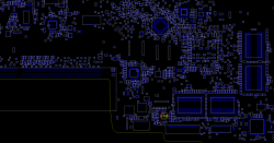
Here's a board view snapshot with U7000 highlighted.
 

Attachments

  • Screen Shot 2012-08-29 at 5.01.52 PM.png
    Screen Shot 2012-08-29 at 5.01.52 PM.png
    53.5 KB · Views: 448

mac-n-sauce

macrumors regular
Jun 25, 2012
209
2
Tampa, Fl
yeah your right the GATE pin is 0v :)
im so sorry for being slow to work this out but
on my photo can you mark where the ic chip is please
because none of the chips on my board correspond to numbers or the schematic.
the schematic is like a maze and i dont really understand it but im learning with your guys exemplary help.


Thanks again

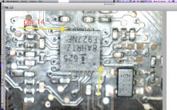
your ic chip is due north of the battery connector. On the bottom of the board. That is the side you see when you take the bottom case off. Attached a photo of my damaged one. Couldn't open your photo.

The other yellow arrow is pin 1
 

Attachments

  • Screen Shot 2012-08-29 at 6.54.29 PM.png
    Screen Shot 2012-08-29 at 6.54.29 PM.png
    2 MB · Views: 729

cmdrdata

macrumors 6502
Jun 10, 2011
377
2
Dallas, Texas, USA
What board is that for?

I believe this is for A1286 15" MBP.

Here's a little tip: as shown in mac-n-sauce's picture, you can see some of the via holes for most of the pins, so if you're probing the chip, sometimes it would be easier to put your tip say on the via holes itself, or on the discrete component (aka resistor or capacitor) instead of the actual IC pins to minimize damage/shorting the pins while probing.
 
Last edited:

Musicsoul78

macrumors regular
Aug 24, 2012
111
0
UK ESSEX
Here's a board view snapshot with U7000 highlighted.

your ic chip is due north of the battery connector. On the bottom of the board. That is the side you see when you take the bottom case off. Attached a photo of my damaged one. Couldn't open your photo.

The other yellow arrow is pin 1

Cmdrdata said i did not need read from pin 4 and 1 anymore just read from the ic.

these are perfect thanks guys will let you know 2 morrow
here my photos
Photo%2024-08-2012%2014%2043%2019.jpg

MAC%20CHARGE.png
 

mac-n-sauce

macrumors regular
Jun 25, 2012
209
2
Tampa, Fl
I believe this is for A1286 15" MBP.

Is that the one that was on this forum? If so it is the late 2008 early 2009 2.53Ghz with dual fans. I think he has the mid 2009 2.53.

Just an update: I r/r the IC chip. Now I have no pulsing magsafe. 6.8v on pin 21
5.7v pin 24.

Starts with battery shorting G3hot. Still no start with magsafe.
Fan ran high speed.
My Q7001(on bottom by LVDS) that I replaced because it had a broken pin1 is not getting the voltage right
Q7000(on top by DC Jack) has pins 1-4 at a fluctuating 16.8v-17.09v
Pin 5 fluctuating as high as .26v
Checked LT4370 pins measured good
The R7020 Measures open. I believe this is located just south west of the Q7001 can you confirm.
 
Last edited:

cmdrdata

macrumors 6502
Jun 10, 2011
377
2
Dallas, Texas, USA
Is that the one that was on this forum? If so it is the late 2008 early 2009 2.53Ghz with dual fans. I think he has the mid 2009 2.53.

Just an update: I r/r the IC chip. Now I have no pulsing magsafe. 6.8v on pin 21
5.7v pin 24.

Starts with battery shorting G3hot. Still no start with magsafe.
Fan ran high speed.
My Q7001(on bottom by LVDS) that I replaced because it had a broken pin1 is not getting the voltage right
Q7000(on top by DC Jack) has pins 1-4 at a fluctuating 16.8v-17.09v
Pin 5 fluctuating as high as .26v
Checked LT4370 pins measured good
The R7020 Measures open. I believe this is located just south west of the Q7001 can you confirm.

R7020 measured open is definitely why you're not able to boot with magsafe NOW. That resistor is the only path that allows DCIN power (aka PPVDCIN_G3H_PRE) to be chopped up/regulated to 12v by Q7020/Q7021. My concern is that previously you were getting 15-17v on pin5 of Q7020, so the fact that R7020 now measures open is probably due to work you did sometimes after seeing that pin5 voltage.
 

mac-n-sauce

macrumors regular
Jun 25, 2012
209
2
Tampa, Fl
R7020 measured open is definitely why you're not able to boot with magsafe NOW. That resistor is the only path that allows DCIN power (aka PPVDCIN_G3H_PRE) to be chopped up/regulated to 12v by Q7020/Q7021. My concern is that previously you were getting 15-17v on pin5 of Q7020, so the fact that R7020 now measures open is probably due to work you did sometimes after seeing that pin5 voltage.

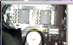
I am attaching photo. I think I had the wrong resistor.
The one in the photo I believe is the R7020 it measured 1.8 on my 200 ohm setting.
 

Attachments

  • Screen Shot 2012-08-29 at 9.05.12 PM.png
    Screen Shot 2012-08-29 at 9.05.12 PM.png
    1.6 MB · Views: 367

cmdrdata

macrumors 6502
Jun 10, 2011
377
2
Dallas, Texas, USA
I am attaching photo. I think I had the wrong resistor.
The one in the photo I believe is the R7020 it measured 1.8 on my 200 ohm setting.

R7020 is a sense power resistor and has very low value, at 0.01 or 0.02 ohm. So the picture you posted is not R7020. BTW, numbers shown in that picture is not resistor number but resistor part number and sometimes resistance value. What you need is a board view file for your Mac (I don't have one and have been asking/looking for one myself.
 

Joan454

macrumors newbie
Aug 29, 2012
5
0
Chris. That is the non pro unibody 2008? I can help you troubleshoot. Send me a pm. You don't seem to have pm enabled on your account.
ht7.jpg
jh88.jpg
dh5.jpg
 

mac-n-sauce

macrumors regular
Jun 25, 2012
209
2
Tampa, Fl
R7020 is a sense power resistor and has very low value, at 0.01 or 0.02 ohm. So the picture you posted is not R7020. BTW, numbers shown in that picture is not resistor number but resistor part number and sometimes resistance value. What you need is a board view file for your Mac (I don't have one and have been asking/looking for one myself.

Are you sure? The package number for that resistor is 0612. I looked it up on Digi-key and it matched.
 

cmdrdata

macrumors 6502
Jun 10, 2011
377
2
Dallas, Texas, USA
Are you sure? The package number for that resistor is 0612. I looked it up on Digi-key and it matched.

Both of my A1278 schematics (K6 and K24 versions) shows R7020 as having a resistance of 0.02 Ohms. If R7020 is 1.8 Ohm, it would have to be handle several amps of current flowing thru it. Package type is just it, has nothing to do with resistance values. It specifies physical size and power dissipation/handling capability. Rnumber is just schematic notation. I've NEVER seen a resistor labeled with Rnumber.

Just a thought: if that one in the picture is R7020, the value is perhaps 0.02 ohm (The designation of R020 on the part could be interpreted as .020). So if you measured that resistance as 1.8 ohm, I'd venture that the pictured resistor is R7020 and it is blown, and what you are measuring is the impedance of the surrounding circuitry.

EDIT: This morning I looked up SMD resistor coding, and here's the URL: http://www.hobby-hour.com/electronics/4-digit-smd-resistors.php. SO it seemed that R020 indeed means 0.02 Ohm !!!! So the picture you posted could be R7020 schematic designation, unless there are more resistors in the LB with that same value. :)
 
Last edited:
Register on MacRumors! This sidebar will go away, and you'll see fewer ads.